
User Manual

5-2
AutoMax Network Communication Option Board
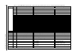
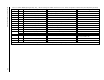
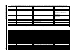
Table 5.2 – FlexPak 3000 Original Register Map, Drop_1: Master Read Registers, BASIC and FULL Connections. Runtime Signal Data (Drive Output Data)
Register Bit Parameter Name (Number) Description Settings
0 Drive status word 1 Bit-packed word containing information on the present status of the drive
0 Drive ready
1Drive running
2 Fault active
3 Drive jogging
4 Forward/reverse command 0=forward; 1=reverse
5 Drive stopping
6 Tune/config input enable loopback 0=disabled; 1=enabled
7 Tune/config update synch. flag loopback (master read)
8 Alarm active
9 In current limit
10 Coast/DB interlock 0=open; 1=closed
11 Customer interlock 0=open; 1=closed
12 Parameter processing error 0=no errors; 1=one or more errors
13 Terminal strip forward/reverse input state (terminal 5)
14 Terminal strip auto/manual input state (terminal 6)
15 Terminal strip fault/alarm reset input state (terminal 10)
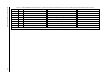
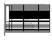
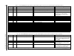
1
SPD SOURCE SELECT OUT (P.193) Selected speed/voltage loop reference value 4095 at TOP SPEED (P.011)
2
SPD LOOP REFERENCE (P.295) Final speed/voltage loop reference value 4095 at TOP SPEED (P.011)
3
SPD LOOP FEEDBACK (P.296) Final speed/voltage loop feedback value after all scaling 4095 at TOP SPEED (P.011)
4
SPD LOOP OUTPUT (P.299) Speed loop PI block output value 4095 at MAXIMUM CURRENT (P.007
5
ARMATURE VOLTAGE (P.289) Armature voltage feedback value 4095 at MOTOR RATED ARM VOLTS (P.009)
6Average
CML feedback CML feedback average over eight CML scans 4095 at MAXIMUM CURRENT (P.007)
7 Network Output Register 1 Value of the parameter selected by
NETW OUT REG 1
SELECT (P.902)
If no valid parameter value selected,
0=motor speed in RPM
8 Network Output Register 2 Value of the parameter selected by NETW OUT REG 2
SELECT (P.903)
If no valid parameter value selected,
0=armature voltage in volts
9 Network Output Register 3 Value of the parameter selected by
NETW OUT REG 3
SELECT (P.904)
If no valid parameter value selected,
0=armature current in amps*10 or amps
10 to 15 Tunable, Configurable and Status Data See table 5.3 on page 5-4.
Runtime signal data are updated by the regulator every 5 msec, unless
FEEDBACK SELECT (P.200) is set to ARMATURE VOLT, in which case the update time is 10 msec.