$ $# !$ " ! & !$ $ ' $" " Receive and Accept the Shipment . . . . . . . . . . . . . . . . . . . . . . . . . . . . . . . . . . . . . . . . . . . . . . . . . . . . . 1:1 Store the Controller . . . . . . . . . . . . . . . . . . . . . . . . . . . . . . . . . . . . . . . . . . . . . . . . . . . . . . . . . . . . . . . . . . 1:1 File a Return Request . . . . . . . . . . . . . . . . . . . . . . . . . . . . . . . . . . . . . . . . . . . . . . . . . . . . . .
5: Troubleshooting General . . . . . . . . . . . . . . . . . . . . . . . . . . . . . . . . . . . . . . . . . . . . . . . . . . . . . . . . . . . . . . . . . . . . . . . . . . . . Wiring Errors . . . . . . . . . . . . . . . . . . . . . . . . . . . . . . . . . . . . . . . . . . . . . . . . . . . . . . . . . . . . . . . . . . . . . . . AĆC Line and Power Input . . . . . . . . . . . . . . . . . . . . . . . . . . . . . . . . . . . . . . . . . . . . . . . . . . . . . . . . . . . . DĆC Motor . . . . . . . . . . .
Table 2Ć1. Controller Model Numbers . . . . . . . . . . . . . . . . . . . . . . . . . . . . . . . . . . . . . . . . . . . . . . . . . . Table 2Ć2. Isolation Transformer Specifications . . . . . . . . . . . . . . . . . . . . . . . . . . . . . . . . . . . . . . . . . . Table 2Ć3. Fuse Requirements . . . . . . . . . . . . . . . . . . . . . . . . . . . . . . . . . . . . . . . . . . . . . . . . . . . . . . . . . Table 2Ć4. Controller Modification Kits. . . . . . . . . . . . . . .
1: Receive and Accept the FlexPak Plus Controller Receive and Accept the Shipment The RelianceR Electric FlexPak Plus SingleĆPhase DĆC Drive (herein referred to as the Controller) has been designed, manufactured and thoroughly tested to provide many years of reliable service. The shipping container in which you received your Controller has been specifically designed to protect it during transportation and handling. Reliance Terms of Sale, in all instances, are Freight On Board (F.O.B.) point of origin.
2: Introduction to the Controller Scope of This Manual This manual familiarizes you with the FlexPak Plus DĆC Controller. It describes receiving, storage, application, implementation and installation procedures and provides an overview of specifications and operations. Read this manual in its entirety before installing and powering the Controller. Observe all danger notes, warning notes, and caution notes; these precautions point out potentially hazardous procedures and conditions.
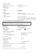
Service Factor Ratings: Service Factor . . . . . . . . . . . . . . . . . . . . . . . . . . . . . 1.0 Continuous Overload Capacity (controller only) . . . . . . . . . . 1.5 of full load rating for one minute Minimum Load . . . . . . . . . . . . . . . . . . . . . . . . . . . . 5% of rated load Service Conditions: Thermal: Chassis . . . . . . . . . . . . . . . . . . . . . . . . . . . . . . . . 55 C Maximum Cabinet . . . . . . . . . . . . . . . . . . . . . . . . . . . . . . . .
FlexPak Plus SingleĆPhase DĆC Controller Description The Reliance Electric FlexPak Plus SingleĆPhase DĆC Controller is a fullĆwave power converter without back rectifier, complete with an analog current minor loop and an analog major loop for armature voltage or speed regulation by tachometer feedback. The product line has been setĆup to be sold as follows (Refer to Table 2Ć1): A. Basic Chassis Controller without Auxiliary Panel: Includes power converter, field supply and regulator.
Table 2Ć2. Isolation Transformer Specifications. HP 1/4 1/2Ć3/4 kVA 0.5 0.5 0.75 0.75 1.5 1 2.0 1Ć1 1/2 3.0 2 5.0 3Ć5 10.
! 14C223 Voltage/Tachometer Follower Enables drive to follow a reference source that is indeĆ pendently generated. DĆ3971 14C224 Torque Taper Allows adjustment of slope and break point of drive speed - torque curves - increases current limit with speed, i.e. center window.
3: Install and Wire The Drive DANGER DANGER ONLY QUALIFIED ELECTRIĆ CAL PERSONNEL FAMILIAR WITH THE CONSTRUCTION AND OPERATION OF THIS EQUIPMENT AND THE HAZĆ ARDS INVOLVED SHOULD INSTALL, ADJUST, OPERATE AND/OR SERVICE THIS EQUIPMENT. READ AND UNDERSTAND THIS MANUAL IN ITS ENTIRETY BEFORE PROCEEDING. FAILURE TO OBSERVE THIS PRECAUTION COULD RESULT IN SEVERE BODILY INJURY OR LOSS OF LIFE. THIS EQUIPMENT IS AT LINE VOLTAGE WHEN AĆC POWER IS CONNECTED.
1. Verify that the motor is the appropriate rating to use with the controller. 2. Install the DĆC motor in accordance with its own installation instructions. 3. Make sure that coupled applications have proper shaft alignment with the driven machine or that belted applications have proper sheave/belt alignment to minimize unnecessary motor loading.
Install A Disconnect DANGER THIS EQUIPMENT IS AT LINE VOLTAGE WHEN AĆC POWER IS CONNECTED. DISCONĆ NECT AND LOCKOUT ALL UNGROUNDED CONDUCĆ TORS OF THE AĆC POWER LINE. FAILURE TO OBSERVE THESE PRECAUTIONS COULD RESULT IN SEVERE BODILY INJURY OR LOSS OF LIFE. 1. Any fused disconnect or circuit breaker in the incoming AĆC line must accommodate a maximum symmetrical AĆC fault current of 5,000 amperes.
NOTES: 3 TACHOMETER T1 (+) 6 These signals must be run in a separate magnetic conduit to minimize the possibility of noise pickup. Use either twisted double or twisted triple conductor wire, 2 twists per inch, stranded copper, AWG #16,600 VAC rated, polyvinyl chloride insulation, with a temperaĆ ture range of 40-105 C (104-221 F) 2 When the Auto/Manual Switch is used, wire 426 is connected to the Auto/Manual Switch rather than the Speed Pot.
DANGER THE USER IS RESPONSIBLE FOR CONFORMING TO THE NEC AND ALL OTHER APPLIĆ CABLE LOCAL CODES WITH RESPECT TO WIRING PRACĆ TICES, GROUNDING, DISĆ CONNECTS AND OVERCURĆ RENT PROTECTION ARE OF PARTICULAR IMPORTANCE. FAILURE TO OBSERVE THIS PRECAUTION COULD REĆ SULT IN SEVERE BODILY INJURY OR LOSS OF LIFE. DANGER THIS EQUIPMENT IS AT LINE VOLTAGE WHEN AĆC POWER IS CONNECTED. DISCONĆ NECT AND LOCKOUT ALL UNGROUNDED CONDUCĆ TORS OF THE AĆC POWER LINE.
isolation transformer, thus reducing or eliminating possible damage to solid state components. With an isolation transformer, the Drive is free of plant power system grounds, providing electrical isolation for the Drive from those grounds. Damaging currents may be avoided in instances where the DĆC output is accidentally grounded or where the DĆC motor circuits go to ground. Reliance offers a series of isolation transformers suitable for use with the FlexPak Plus Drive. Refer to Table 2Ć2.
ÉÉÉÉÉ ÉÉÉÉÉ ÉÉÉÉÉ ÉÉÉÉÉÉÉÉÉÉ ÉÉÉÉÉÉÉ ÉÉÉÉÉÉÉÉÉÉ ÉÉÉÉÉÉÉ ÉÉÉÉÉÉÉÉÉÉ ÉÉÉÉÉÉÉ : CLOSED START Switch STOP Switch CLOSED FM or RM contactor CLOSED PULL IN DROP OUT PULL IN CR Relay (enables drive) 20 msec 8 msec DROP OUT 30 msec (min) 8 msec Figure 3Ć4. Armature Contactor Sequencing and Regulator Start/Stop Timing. Control transformer secondary winding 481 482 10 FM 36 fd STATIC LOGIC CR FM 65 38 approx.
Control transformer secondary winding 481 482 fd 10 FM 36 RM STATIC LOGIC CR 36 approx. 24 VDC MOTOR OVERLOAD 132 START STOP 220 MFD FORWARD RM 38 32 66 39 139 39 66 38 1 FM 220 MFD RUN CR - Pin Connection - Wire Terminal Board NOTE: FM 35 JOG 1 38 65 67 65 139 1 RM REVERSE FM & RM Contactor may not be supplied by Reliance Figure 3Ć6. Reversing Drive Control Circuit.
The userĆsupplied field wiring conductors should be drawn into the chassis. Route them as indicated in Figure 3Ć3. Move them to the upper screws on 2TB and connect F1/F2 according to the label or Figure 3Ć7. In this configuration (see Figure 3Ć8), the J4 jumper on the Regulator Board is NOT to be cut, the reference input is through terminal 426 to the LVTU. The J4 Jumper is only removed when the reference is brought in to terminal 126.
BUFFER BOARD B/M 0Ć57005 REGULATOR BOARD B/M 0Ć57100 MAX SPEED (P2) +11.2v 28 28 MIN SPEED (P1) 20 20 126 126 Common J4 BUFFER ADD JUMPER FROM 326 TO 426 ON THE BUFFER BOARD 426 26 326 326 TYPICAL REFERENCE KIT + LVTU J1 BUFFER 26 FOLLOWER REFERENCE INPUT - 326 57 Common Figure 3Ć9. Reference Circuit for Follower Reference Kit without the use of the Manual Operator's Reference Option.
BUFFER BOARD B/M 0Ć57005 REGULATOR BOARD B/M 0Ć57100 MAX SPEED (P2) +11.2v OPERATOR'S SPEED REF POT 28 28 MIN SPEED (P1) 5K MANUAL 20 20 126 126 BUFFER AUTO/MANUAL SWITCH 426 26 326 326 Common J4 LVTU AUTO TYPICAL REFERENCE KIT + J1 BUFFER 26 FOLLOWER REFERENCE INPUT - 326 57 Common Figure 3Ć10. Reference Circuit for Follower Reference Kit with the use of the Manual Operator's Reference Option and an Auto/Manual Switch.
This section details the startĆup and adjustment for the basic FlexPak Plus Drive as an armature voltage Remove J9 if using Reversing Contactor Place 5Ćwire connector from Reversing Contactor here. Auxiliary M connects here Place 3Ćwire connector from Auto Reversing Module here. 56 BRN 382 C E G J L N Q 57 S 99 U 71 20 26 28 326 126 26 65 66 39 67 35 38 32 B XFORMER D ORG 139 BLU 61 62 60 AUX.M.
DANGER ONLY QUALIFIED ELECTRIĆ CAL PERSONNEL FAMILIAR WITH THE CONSTRUCTION AND OPERATION OF THIS EQUIPMENT AND THE HAZĆ ARDS INVOLVED SHOULD INSTALL, ADJUST AND/OR SERVICE THIS EQUIPMENT. READ AND UNDERSTAND THIS MANUAL IN ITS ENTIREĆ TY BEFORE PROCEEDING. FAILURE TO OBSERVE THIS PRECAUTION COULD REĆ SULT IN SEVERE BODILY INJURY OR LOSS OF LIFE. DANGER THIS EQUIPMENT IS AT LINE VOLTAGE WHEN AĆC POWER IS CONNECTED. DISCONĆ NECT AND LOCKOUT ALL UNGROUNDED CONDUCĆ TORS OF THE AĆC POWER LINE.
I FDBK. RED 45 ARM. 47 G2 L2 FDBK. G3 47 G4 47 L1 G1 COM MODE SELECTION JUMPER FDBK. C T A 192193 25 15 10 7.5 5 AMPS 3.7 J8 2.5 COM J2 87 86 CURRENT SCALING JUMPER CURRENT SCALING JUMPER CONNECTIONS REGULATION MODE CONNECTIONS Figure 4Ć2. Drive Current Scaling Setup. Regulation Mode Selection The FlexPak Plus Drive has three modes of regulation; A = Speed Regulation by Armature Voltage, T = Speed Regulation by Tachometer or C = Counter EMF Feedback.
Table 4Ć2. Control Power Voltages. Function Unregulated +20 VDC Unregulated Ć20 VDC Regulated +11.2 VDC Regulated Ć11.2 VDC Drive SetĆUp Procedure Basic Regulator Maximum Safe Operating Adjustments The following adjustments are available on the Basic Regulator (see Figure 4Ć3): Terminal(s) /Pin(s) 256 271 56 71 Nominal Values (VDC) +20 VDC +5% Ć20 VDC +5% +11.2 VDC +5% Ć11.2 VDC +5% CAUTION: The following adjustĆ ments are maximum safe operĆ ating ranges.
Verify the Correct Direction of Motor Rotation Connect the regulator mode jumper to the A" position. (This initially sets up the drive as a voltage regulator for purposes of start up. Later on you may need to move the jumper to the T" position if your drive is to be speed regulated.) Set the IR COMP" rheostat to zero (fully CCW). Assuming that the drive is using an operator's station similar to the one shown in figure 3Ć3: Set the operators speed pot to zero". If a torque pot is used, set it fully CW.
See Figure 4Ć4 and Figure 4Ć5 for zero speed circuit configurations. Controllers with P/N 57100 regulators that do not have a J10 jumper can achieve zero minimum speed by turning the minimum speed rheostat fully counterĆclockwise. Controllers that have a J10 jumper can achieve zero minimum speed by moving the J10 jumper between K71 and K72, and turning the MIN SPD rheostat fully counterĆclockwise. (See Figure 4Ć5.
Adjusting Maximum Speed 1. Initially set the MAX. SPD. potentiometer on the Regulator Board fully counterĆclockwise. This should prevent the motor from overspeeding with the Operator's Speed Potentiometer set at 100%. 2. Gradually increase the Operator's Speed Potentiometer to 100%. Observe that the motor and drive machine do not exceed their maximum safe speed. 3. Using a suitable screwdriver, adjust the MAX. SPD. potentiometer clockwise until 100% motor speed is obtained.
Table 4Ć3. Initial/Final Adjustment Settings Potentiometers MAX. SPD. MIN. SPD ACC. DEC. I LIMIT IR COMP Jumpers Feedback1 Current Scaling J42 J5, J63 J7, J84 J95 Initial Setting (Factory) Fully CCW (Dot 1) Fully CCW (Dot 1) Fully CCW (Dot 1) Fully CCW (Dot 1) 150% (Dot 7) Fully CCW (Dot 1 = 0%) A 2.5 Final Setting (User) Installed Installed Installed Installed 1> AĆCOM is the standard connection for Armature Feedback; Factory Setting.
5: Troubleshooting General AĆC Line and Power Input DANGER ONLY QUALIFIED ELECTRIĆ CAL PERSONNEL FAMILIAR WITH THE CONSTRUCTION AN OPERATION OF THIS AND THE HAZARDS INVOLVED SHOULD INSTALL, ADJUST, AND/OR SERVICE THIS EQUIPMENT. READ AND UNĆ DERSTAND THIS MANUAL IN ITS ENTIRETY BEFORE PROĆ CEEDING. FAILURE TO OBSERVE THIS PRECAUTION COULD RESULT IN SEVERE BODILY INJURY OR LOSS OF LIFE. This Section details troubleshooting information for the FlexPak Plus Single Phase DĆC Drive.
DANGER SOME OF THE FOLLOWING CHECKS AND PROCEDURES REQUIRE THE POWER TO BE ON. EXERCISE EXTREME CARE AS HAZARDOUS VOLTAGE EXISTS. FAILURE TO OBSERVE THIS PRECAUTION COULD RESULT IN SEVERE BODILY INJURY OR LOSS OF LIFE. Start Note #1: Contact local sales/service office. *Ground conditions = 500 KĆOhms or less to ground.
DANGER SOME OF THE FOLLOWING CHECKS AND PROCEDURES REQUIRE THE POWER TO BE ON. EXERCISE EXTREME CARE AS HAZARDOUS VOLTAGE EXISTS. FAILURE TO OBSERVE THIS PRECAUTION COULD RESULT IN SEVERE BODILY INJURY OR LOSS OF LIFE. Start Note #1: Contact local sales/service office. Remove AĆC power at disconnect. Remove leads A1, A2 * Check motor leads A1 and A2 for grounds *Ground conditions = 500 KĆOhms or less to ground.
DANGER SOME OF THE FOLLOWING CHECKS AND PROCEDURES REQUIRE THE POWER TO BE ON. EXERCISE EXTREME CARE AS HAZARDOUS VOLTAGE EXISTS. FAILURE TO OBSERVE THIS PRECAUTION COULD RESULT IN SEVERE BODILY INJURY OR LOSS OF LIFE. Start Note #1: Contact local sales/service office. Apply AĆC Power and check for proper line voltage between terminals 51 and 52. Do you have correct voltage ? No Do you have an open circuit ? Check for open fuses/disconnect Yes No Yes Problem is with AĆC line voltage supply.
! ! # ! " " 3B Is there a Yes thermostat/jumper wired there? Remove power from drive and check for cotinuity between terminals 32 and 132. Thermostat or jumper is malfunctioning, corĆ rect the problem. No Is there continuity? Check for a motor therĆ mostat or a jumper wired to terminals 32 and132.
DANGER SOME OF THE FOLLOWING CHECKS AND PROCEDURES REQUIRES THE POWER TO BE ON. EXERCISE EXTREME CARE AS HAZARDOUS VOLTAGE EXISTS. FAILURE TO OBSERVE THIS PRECAUTION COULD RESULT IN SEVERE BODILY INJURY OR LOSS OF LIFE. Start Note: #1: Contact local sales/service office. *Reference the layout of the regulator board for PIN location. **The center arm switch should go to PIN 35 and the run position of the switch should connect to the common point between the start/stop pushbutton.
DANGER SOME OF THE FOLLOWING CHECKS AND PROCEDURES REQUIRE THE POWER TO BE ON. EXERCISE EXTREME CARE AS HAZARDOUS VOLTAGE EXISTS. FAILURE TO OBSERVE THIS PRECAUTION COULD RESULT IN SEVERE BODILY INJURY OR LOSS OF LIFE. Start Note #1: Contact local sales/service office. Check for speed reference 0 to 8 VDC between terminals 126 and 57 (common). Is reference voltage present? Check DĆC Bus voltage 0 to 90, or 180 VDC between terminals 47 and 45.
DANGER SOME OF THE FOLLOWING CHECKS AND PROCEDURES REQUIRE THE POWER TO BE ON. EXERCISE EXTREME CARE AS HAZARDOUS VOLTAGE EXISTS. FAILURE TO OBSERVE THIS PRECAUTION COULD RESULT IN SEVERE BODILY INJURY OR LOSS OF LIFE. A From previous page Note #1: Contact local sales/service office.
DANGER SOME OF THE FOLLOWING CHECKS AND PROCEDURES REQUIRE THE POWER TO BE ON. EXERCISE EXTREME CARE AS HAZARDOUS VOLTAGE EXISTS. FAILURE TO OBSERVE THIS PRECAUTION COULD RESULT IN SEVERE BODILY INJURY OR LOSS OF LIFE. Note #1: Contact local sales/service office. *Install a jumper between terminal 26 and 126. From previous page C Has jumper been cut or removed? Yes * Correct the problem Fixed? Yes Done No No See Note #1 Replace Regulator Board Fixed? Yes Done No See Note #1 Figure 5Ć8.
DANGER SOME OF THE FOLLOWING CHECKS AND PROCEDURES REQUIRES THE POWER TO BE ON. EXERCISE EXTREME CARE AS HAZARDOUS VOLTAGE EXISTS. FAILURE TO OBSERVE THIS PRECAUTION COULD RESULT IN SEVERE BODILY INJURY OR LOSS OF LIFE. D From previous 2 pages Note #1: Contact local sales/service office.
DANGER THE FOLLOWING CHECKS AND PROCEDURES REQUIRE THE POWER TO BE ON. EXERCISE EXTREME CARE AS HAZARDOUS VOLTAGE EXISTS. FAILURE TO OBSERVE THIS PRECAUTION COULD RESULT IN SEVERE BODILY INJURY OR LOSS OF LIFE. Start If using TACH feedback, change feedback selection jumper to the A" position for armature voltage feedback and restart the drive. Does motor still runaway? Yes Remove TACH leads from the TACH feedback kit. Measure voltage of TACH. Compare TACH voltage to RPM speed of motor being driven.
The spare or replacement parts for the FlexPak Plus DĆC Drive covered in this manual are listed in Table 6Ć1. This list consists of the more common parts along with part numbers and quantities actually used in the controller.
A: Quick Reference Guide DANGER DANGER DANGER ONLY QUALIFIED ELECĆ TRICAL PERSONNEL FAĆ MILIAR WITH THE CONSTRUCTION AND OPĆ ERATION OF THIS EQUIPĆ MENT AND THE HAZARDS INVOLVED SHOULD ADJUST, OPERATE AND/OR SERVICE THIS EQUIPMENT. READ AND UNDERSTAND THE BASE INSTRUCTION MANUAL IN ITS ENTIRETY BEFORE PROĆ CEEDING. FAILURE TO OBĆ SERVE THIS PRECAUTION COULD RESULT IN SEVERE BODILY INJURY OR LOSS OF LIFE.
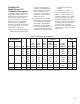
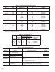
Table AĆ1. Controller Model Numbers Basic 14C50 Complete 14C101 14C51 14C102 14C52 14C103 14C53 14C104 1Standard 2Maximum Transf. KVA Optional Model Number HP 1/4 1/3 1/2 3/4 1/2 3/4 1 1 1/2 2 3 5 VAC 115 115 115 115 230 230 230 230 230 230 230 AĆC Amps (RMS) 3.5 5.2 7.0 10.5 3.5 5.2 7.0 10.5 14.0 21.0 35.0 DĆC Arm. (Volts) 90 90 90 90 180 180 180 180 180 180 180 DĆC Arm. Amps Avg. 2.5 3.7 5.0 7.5 2.5 3.7 5.0 7.5 10.0 15.0 25.
Table AĆ3. Fuse Requirements. Dual Element Class K5, RK5, 250VAC Fuse HP 1/4Ć3/4 1/2Ć1 1/2 2Ć3 5 1Install AĆC Line Volts 115 230 230 230 Quantity 11 2 2 2 AMP 15 15 30 50 Reliance Part Number 64676Ć1W 64676Ć1W 64676Ć1Z 64676Ć1AD fuse in input line L1 (hot line). Table AĆ4. Controller Modification Kits. Kit Model Number 14C214 14C215 14C216 Kit Name Dynamic Braking Resistor 1/4 to 1/2 HP @115 VAC 2.0 to 3.
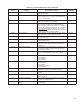
Table AĆ4. Controller Modification Kits. (Continued) Kit Model Number Kit Name 9C200 Operator's Station 9C300 Operator's Station 9C42 Functional Description Standard NEMA 4 control station; Start Pushbutton Stop Pushbutton Run/Jog Switch Speed Setting Pot Standard NEMA 4 control station; Start Pushbutton Stop Pushbutton Run/Jog Switch Forward/Reverse Switch Speed Setting Pot - Speed Potentiometer 2 watt, 5K ohm potentiometer with knob for separate mounting.
NOTES: 3 TACHOMETER T1 (+) 6 These signals must be run in a separate magnetic conduit to minimize the possibility of noise pickup. Use either twisted double or twisted triple conductor wire, 2 twists per inch, stranded copper, AWG #16,600 VAC rated, polyvinyl chloride insulation, with a temperaĆ ture range of 40-105 C (104-221 F) 2 When the Auto/Manual Switch is used, wire 426 is connected to the Auto/Manual Switch rather than the Speed Pot.
ÉÉÉÉÉ ÉÉÉÉÉ ÉÉÉÉÉ ÉÉÉÉÉÉÉÉÉÉ ÉÉÉÉÉÉÉ ÉÉÉÉÉÉÉÉÉÉ ÉÉÉÉÉÉÉ ÉÉÉÉÉÉÉÉÉÉ ÉÉÉÉÉÉÉ : CLOSED START Switch STOP Switch CLOSED FM or RM contactor CLOSED PULL IN DROP OUT PULL IN CR Relay (enables drive) 20 msec 8 msec DROP OUT 30 msec (min) 8 msec Figure AĆ6. Armature Contactor Sequencing and Regulator Start/Stop Timing. Control transformer secondary winding 481 482 10 FM 36 fd STATIC LOGIC CR FM 65 38 approx.
Control transformer secondary winding 481 482 10 FM 36 RM fd STATIC LOGIC CR 36 approx. 24 VDC MOTOR OVERLOAD 132 STOP START FORWARD RM 38 32 66 39 39 66 38 220 MFD 139 FM 1 220 MFD RUN - Pin Connection - Wire Terminal Board NOTE: FM 35 JOG 67 65 38 CR 1 65 REVERSE FM & RM Contactor may not be supplied by Reliance RM 1 139 Figure AĆ8. Reversing Drive Control Circuit.
BUFFER BOARD B/M 0Ć57005 REGULATOR BOARD B/M 0Ć57100 MAX SPEED (P2) +11.2v OPERATOR'S SPEED REF POT 28 28 MIN SPEED (P1) 5K Common 20 20 126 126 BUFFER 426 J4 LVTU 26 Figure AĆ10. Reference Circuit for Manual Operator's Speed Reference Circuit. BUFFER BOARD B/M 0Ć57005 REGULATOR BOARD B/M 0Ć57100 MAX SPEED (P2) +11.
BUFFER BOARD B/M 0Ć57005 REGULATOR BOARD B/M 0Ć57100 MAX SPEED (P2) +11.2v OPERATOR'S SPEED REF POT 28 28 MIN SPEED (P1) 5K MANUAL 20 20 126 126 BUFFER AUTO/MANUAL SWITCH 426 26 326 326 Common J4 LVTU AUTO TYPICAL REFERENCE KIT + J1 BUFFER 26 FOLLOWER REFERENCE INPUT - 326 57 Common Figure AĆ12. Reference Circuit for Follower Reference Kit with the use of the Manual Operator's Reference Option and an Auto/Manual Switch.
Remove J9 if using Reversing Contactor Place 5Ćwire connector from Reversing Contactor here. Auxiliary M connects here Place 3Ćwire connector from Auto Reversing Module here. 56 BRN 382 C E G J L N Q 57 S 99 U 71 20 26 28 326 126 26 65 66 39 67 35 38 32 B XFORMER D ORG 139 BLU 61 62 60 AUX.M. K YEL M RED THM 39 PUR Remove J7 and J8 if using Torque Taper Kit. J9 47 G2 L2 FDBK. 192193 L1 G1 COM 25 15 J6 J8 FDBK.
Table AĆ6. Control Power Voltages. Terminal(s) /Pin(s) 256 271 56 71 Function Unregulated +20 VDC Unregulated Ć20 VDC Regulated +11.2 VDC Regulated Ć11.2 VDC Nominal Values (VDC) +20 VDC +5% Ć20 VDC +5% +11.2 VDC +5% Ć11.2 VDC +5% I FDBK. RED 45 ARM. 47 G2 L2 FDBK. G3 47 G4 47 L1 G1 COM MODE SELECTION JUMPER FDBK. C T A 192193 25 15 10 7.5 5 AMPS 3.7 J8 2.5 COM J2 87 86 CURRENT SCALING JUMPER CURRENT SCALING JUMPER CONNECTIONS REGULATION MODE CONNECTIONS Figure AĆ14.
J8 3.7 COM 2.5 FDBK. C T A J7 319 0 MAX. SPD. 219 56 CLIP FOR 85 50HZ 57 0 MIN. SPD. ACCEL. SPD. 17 0 DECEL. SPD.
Figure AĆ17. Zero Minimum Speed Correction Table AĆ7. Initial/Final Adjustment Settings Potentiometers MAX. SPD. MIN. SPD ACC. DEC. I LIMIT IR COMP Jumpers Feedback1 Current Scaling J42 J5, J63 J7, J84 J95 Initial Setting (Factory) Fully CCW (Dot 1) Fully CCW (Dot 1) Fully CCW (Dot 1) Fully CCW (Dot 1) 150% (Dot 7) Fully CCW (Dot 1 = 0%) A 2.5 Final Setting (User) Installed Installed Installed Installed 1> AĆCOM is the standard connection for Armature Feedback; Factory Setting.
A:17 Figure AĆ19. Controller Technical Data.
B: GLOSSARY OF TERMS Altitude: The atmospheric altitude (height above sea level) at which the motor or controller will be operating. Armature: The portion of the DĆC motor which rotates. Rated Full Load Current: Armature current in amperes. Armature Resistance: Measured in ohms at 25 degrees Celsius (cold). Base Speed: The speed which a DĆC motor develops at rated armature and field voltage with rated load applied.
Service Factor (SF): When used on a motor nameplate, a number which indicates how much above the nameplate rating a motor can be loaded without causing serious degradation, (i.e. a 1.15 SF can produce 15% greater torque than a 1.0 SF rating of the same motor). Tachometer: A small generator normally used as a rotational speed sensing device. Tachometers are typically attached to the output shaft of a motor requiring close speed regulation.
AĆC Line and Power Input 5:1 Adjusting Minimum Speed 4:5 Adjusting Maximum Speed 4:7 Basic Regulator Maximum Safe Operating Adjustment 4:4 Motor Ground Check 4:2 Optional Kits 5:1 Power Off Inspection 4:2 Power On 4:3 Controller Mounting Dimensions 3:2 Current Limit 4:7 DĆC Motor 5:1 Determination of Tachometer Output Polarity 4:5 Drive Deceleration Time 4:7 Drive Acceleration Time 4:7 Drive Identification Nameplate 1:1 Drive SetĆup Procedure 4:4 Receive and Accept the FlexPak Cont
U.S. Drives Technical Support Tel: (1) 262.512.8176, Fax: (1) 262.512.2222, Email: support@drives.ra.rockwell.com, Online: www.ab.com/support/abdrives Trademarks not belonging to Rockwell Automation are property of their respective companies. Publication D-3900-6 - June 1994 Copyright © 1994 Rockwell Automation, Inc. All Rights Reserved. Printed in USA.