FlexPak 3000 Power Module SW-Version 4.2 Instruction Manual C UL R UL R Europe Manual Part No: 899.07.41 Firmware Part No: 790.30.
.
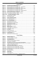
TABLE OF CONTENTS Table of Contents 1.0 General Notes 1.1 1.2 1.3 1.4 Safety Instructions.................................................................................................... 1-1 General Notes .......................................................................................................... 1-2 Manual Scope ............................................................................................................1.2 Related Documentation ............................................
TABLE OF CONTENTS 4.0 Drive Setup and Adjustment 4.1 4.2 4.3 4.4 4.5 4.6 4.7 4.8 4.9 4.10 4.11 4.12 4.13 4.14 4-1...4-16 General ..................................................................................................................... 4-1 Test Equipment Needed ........................................................................................... 4-1 Power Off Inspection.................................................................................................
TABLE OF CONTENTS 7.0 Troubleshooting/Diagnostics 7.1 7.2 7.3 7.4 7.5 7.6 7.7 7-1..7-8 General .................................................................................................................... Wiring Errors ............................................................................................................ AC Line and Power Input.......................................................................................... DC Motor....................................................
TABLE OF CONTENTS List of Figures Figure 2.1 - FlexPak 3000 Functional Block Diagram .............................................................. 2-7 Figure 2.2 - Operator Interface Module (OIM).......................................................................... 2-9 Figure 3.1 - Mounting Dimensions for FlexPak 3000, 25 and 60 A ....................................... 3-2 Figure 3.2 - Mounting Dimensions for FlexPak 3000, 150 A ................................................... 3-3 Figure 3.
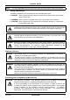
GENERAL NOTES NOTE: 1.1 The term converter is used throughout this manual for the FlexPak 3000 Power Module. Safety Instructions DANGER, WARNING, and CAUTION point out potential trouble areas. • A DANGER alerts a person that high voltage is present which could result in severe bodily injury or loss of life. • A WARNING alerts a person to potential bodily injury if procedures are not followed.
GENERAL NOTES 1.2 General Notes Copyright © Copyright Rockwell Automation AG, 2000 Each reproduction of this manual may be prosecuted. The copyright of the user's manual remains at Rockwell Automation AG, CH-6036 Dierikon. Trade mark Reliance® is a registered trade mark of Rockwell Automation AG. SW-Version This manual is valid for Regulator Software Versions 4.1 and 4.2. Regulator SW Versions can be read in Parameter 794. 1.
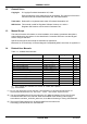
INTRODUCTION TO THE DRIVE 2.0 Introduction to the Drive This section provides specifications and a description of the FlexPak 3000 Drive. 2.1 Drive Identification 2.1.1 Nameplate The FlexPak 3000 drive has a nameplate on the right side of the carrier that identifies the drive by its specific Hardware and Software Part Numbers and applicable AC input power and DC output power data. Refer to this nameplate example.
INTRODUCTION TO THE DRIVE 2.2 Drive Specifications 2.2.1 AC-Line Considerations Requirement 1) Limiting the AC line symmetrical fault current to 100 kA (max. for fuses) or values acc. table below for UL, cUL, as well as limiting commutation notches at the line input (terminals 1U, 1V, 1W). 2) Limiting the A-C line symmetrical fault current (RMS) at the field rectifier input (terminals 3V, 3W) to 10 kA. Measures Always adding an impedance in the line input.
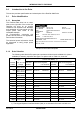
INTRODUCTION TO THE DRIVE 2.2.3 Input Voltage and Frequency Ratings: Nominal voltage for three-phase at terminals 1U, 1V, 1W and 2U, 2V, 2W On units 25, 60, 150 A ...................................................... 200 - 500 VAC at 50 Hz 200 - 460 VAC at 60 Hz On units 500 V, 250, 450, 800, 1200, 1600 and 2000 A .................... 200 - 500 VAC On units 575 V, 60 Hz, 1600 A........................................................... 300 - 575 VAC On units 690 V, 50 Hz, 1600 A..........................
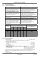
INTRODUCTION TO THE DRIVE 2.2.7 Regulation (with 95% load change): Table 2-2 - Tachometer Speed Regulation Speed Change with 95% Load Change Regulation Arrangement Armature Voltage Regulation with IR Comp. Speed Change from All other Variables 2-3 % Part Number 15% Not applicable. 2% - Closed Loop with Analog tach 1% with Pulse tach 1) 0.01% 0.01% 762.70.00 1) Optional Pulse Tachometer Feedback kit required (See instruction manual 49’1343). 2.2.8 Speed Range: Operator's Speed Adjustment......
INTRODUCTION TO THE DRIVE 2.3 Drive Input/Output Specifications The following sections describe drive inputs and outputs. Refer to section 3.8 for terminal strip connections and wiring diagrams. 2.3.1 Logic Inputs: CAUTION: Connecting an external power source to any of the +24 volt connections (terminals 1, 7, 11, and 14) on the regulator board terminal strip will damage the drive. DO NOT connect the external power source to the +24 volt connections on the regulator board terminal strip.
INTRODUCTION TO THE DRIVE Analog Tachometer Feedback Tach Voltage at Top Speed ......................................................................... 10 - 250 V DC NOTE: J14 Jumper position and connection of DC-Tachometer must correspond. Top Speed Tach Volts 2.3.4 < 16 V < 31 V < 62 V < 125 V < 250 V Jumper J14 LOW LOW LOW HI HI Jumper J11 16 31/125 62/250 31/125 62/250 Analog Outputs: The two metering analog outputs are available at regulator board terminals 24, 25 and 26.
INTRODUCTION TO THE DRIVE 2.4 Drive Description The drive is a full-wave power converter without back rectifier, complete with a digital current minor loop and a digital major loop for armature voltage or speed regulation by tachometer feedback. Figure 2-1 shows a block diagram of the Drive. The Drive employs a wireless construction and uses a keypad for drive setup, including parameter adjustments and unit selection, monitoring and diagnostics.
INTRODUCTION TO THE DRIVE Rockwell Automation offers modification kits that broaden the application range of the drive. A summary of these kits is presented in the following Table 2-4. Related Instruction Manuals are listed in Table 1-1, Section 1.4. Table 2-4 - Drive Modification Kits Name Description Pulse Tacho Allows for digital pulse tachometer speed feedback on high Feedback Kit PTK performance regulation applications. (Kit includes cable). Part Number 762.70.
INTRODUCTION TO THE DRIVE 2.5 Controls/Indicators See Figure 2-2 for location of the controls and indicators for the Keypad OIM. Drive fault and status indicators are listed in Table 2-5.
INTRODUCTION TO THE DRIVE Table 2-5 - OIM Drive Fault and Status Indicators Indicators Description Fault A condition or conditions exists in the drive which stopped it or prevents it from running. When a fault occurs, the type of fault and further instructions are displayed on the OIM display. Alarm An alarm does not prevent the drive from running but alerts the user that a condition exists that could cause a fault in the future.
INTRODUCTION TO THE DRIVE FlexPak 3000 Main Menu !! ➤Quick Start Drive Reference Speed/Voltage Loop (SPD) #Current Minor Loop (CML) PROGRAM KEYPAD MANUAL FORWARD • Pressing this key will display the following screen: MOTOR SPEED ARM VOLTS MOTOR LOAD KEYPAD REF: MONITOR 0 0 0 0 KEYPAD RPM VOLTS %FLA RPM MANUAL !! FORWARD This screen allows the user to change the drive's setpoint (KEYPAD REF) when the CONTROL SOURCE SELECT is set to KEYPAD and the drive is in manual mode.
INTRODUCTION TO THE DRIVE This key allows the operator to review and clear logs (fault and alarm), reset faults, clear the alarm indicator and display fault history and diagnostic information for servicing the drive. The state of this key (FAULT, ALARM or DIAGS) is shown on the LCD directly above the key.
INTRODUCTION TO THE DRIVE MENU HELP FlexPak 3000 Main Menu Select the appropriate menu item with the UP/DOWN arrow keys and the ENTER key. You can use CANCEL at any time to return to the previous menu level. PROGRAM KEYPAD MANUAL !! !! FORWARD A # displayed at the bottom left of the text indicates that more text is available. Press the down ! key to scroll up the remaining text for viewing.
INTRODUCTION TO THE DRIVE Moves the cursor left or right in parameter modification (value entry) screens to allow digit selection for parameter value setting. Left (⇐) accesses the Language Selection menu at any menu level but not at parameter modification screens. See section 4.13 of this instruction manual for further details on the Language Selection menu. Right (⇒) accesses the Contrast Adjustment screen at any menu level but not at parameter modification screens. See section 4.
INTRODUCTION TO THE DRIVE .JOG --------- RUN STOP -----RESET # 49’1340 e Active only when in KEYPAD control mode. This key causes the drive reference to ramp up at the JOG ACCEL/DECEL rate to jog speed. When this key is released, the drive reference ramps to zero at the same rate. If the drive status indicators show that the drive is "not ready", this request will be ignored. Active only when in KEYPAD control mode. This key allows the motor to accelerate to the speed reference setpoint.
. 2-16 FlexPak 3000 49’1340 e
INSTALLATION AND WIRING 3.0 Install and Wire the Drive DANGER The user is responsible for conforming to all other applicable standards. Wiring practices, grounding, disconnects, and overcurrent protection are of particular importance. Size and install all wiring in conformance with the applicable standards. Failure to observe this precaution could result in severe bodily injury or loss of life. DANGER This equipment must be connected to a power source for which it was designed.
INSTALLATION AND WIRING 269 25 25 219 7.0 14.0 12 Power connections Terminals for 25 A Unit 386 400 2 Motor 1D, 1C 6 mm 1.4 Nm AC-Line 1U, 1V, 1W 6 mm 1.4 Nm Prot. earth PE 6 mm 1.4 Nm 2 2 130 Power connections Terminals for 60 A Unit 136 185 107 7 25 219 25 2 Motor 1D, 1C 16 mm 2.5 Nm AC-Line 1U, 1V, 1W 16 mm 2.5 Nm Prot. earth PE 16 mm 2.5 Nm 2 2 MAX.
INSTALLATION AND WIRING 269 25 69.5 25 219 32.5 32.5 32.5 32.5 69.5 ø8.5 7.0 12 14.0 1U 1C 1V 1D 1W Power Connections on 1-Quadrant Units S-6 69.5 36 185 29 29 36 69.5 ø8.5 386 400 428 1C 1U 1V 1W 1D 130 Power Connections on 4-Quadrant Units S-6R 136 107 Power Connections 7 25 25 219 MAX. 250 Motor 1D, 1C Bus bars 2 90 mm AC-Line 1U,1V,1W Bus bars 2 60 mm Prot. Earth Terminals 35 mm Torque 2.
INSTALLATION AND WIRING Power connections for 250 A Unit Motor 1D, 1C Bus bars 25 x 5, Hole 11 mm AC-Line 1U, 1V, 1W Bus bars 20 x 5, Hole 11 mm Prot. earth PE Bolt M10, Torque 15 Nm Power connections for 450 A Unit Motor 1D, 1C Bus bars 40 x 5, Hole 14 mm AC-Line 1U, 1V, 1W Bus bars 30 x 5, Hole 14 mm Prot.
INSTALLATION AND WIRING 25 Ø 1) 1) Holes for lifting hooks Power connections Motor 1D, 1C Bus bars 50 x 10, Hole 13.5 mm AC-Line 1U, 1V, 1W Bus bars 40 x 10, Hole 13.5 mm Protection earth PE Bolt M12 Torque 15 Nm Weight: 83 kg Cooling air: 814 m3/h Air flow direction: Minimum clearances for air circulation: from bottom to top 100 mm Figure 3-4: Mounting Data for 800 A Drives.
INSTALLATION AND WIRING 455 515 400 6 14 25 Ø 1) 240 21 190 49 50 = 40 100 = DC OUTPUT M12 60 317 197 975 200 52 905 M12 50 = 100 40 = 185 DC OUTPUT 138 418 130 154 26 26 = 60 89.5 60 89.5 60 160 = 1) Holes for lifting hooks Power connections 200 Motor 1D, 1C Bus bars 100 x 10, Drilling 4 x M12 AC-Line 1U, 1V, 1W Bus bars 60 x 10, Drilling 2 x 13,5 mm Prot.
INSTALLATION AND WIRING 25 Ø 1) 1) Holes for lifting hooks Power connections 200 Motor 1D, 1C Bus bars 120 x 10, Drilling 4 x M12 Torque 25 Nm AC-Line 1U, 1V, 1W Bus bars 96 x 10, Drilling 4 x 14 mm Prot. earth PE Bus bar 60 x 10, Drilling 2 x 14 mm, Weight: Cooling air: 196 kg 2000 m3/h Air flow direction: from bottom to top Minimum clearances for free air circulation: 100 mm Figure 3-6: Mounting Data for FlexPak 2000A, 500V.
INSTALLATION AND WIRING 3.4 Install a Line Reactor or Transformer CAUTION Distribution system capacity above the maximum permitted system kVA, as well as limitation of commutation notches, requires always adding an impedance at line input (terminals 1U, 1V, 1W). You can use a 3-phase line reactor with 2% voltage drop minimum (refer to Table 8-6) or other means of adding similar impedance (e.g. matched isolation or auto transformer).
INSTALLATION AND WIRING 3.6 Install the Motor 1. Verify that the motor is the appropriate rating to use with the drive. 2. Install the DC motor in accordance with its installation instructions. 3. Make sure that coupled applications have proper shaft alignment with the driven machine or that belted applications have proper sheave/belt alignment to minimize unnecessary motor loading. 4. If the motor is accessible while it is running, install a protective guard around all exposed rotating parts. 5.
INSTALLATION AND WIRING 3.8 Wire the Drive 3.8.1 Ground the Drive and Enclosure, the Motor and the Operator's Control Station (Refer to page 18, Recommended Lugs for Grounding FlexPak Drives in UL / cUL Version) 1. Run a suitable equipment grounding conductor unbroken from either drive ground point (terminal PE or ground stud) to the plant ground (grounding electrode). 2. Connect a suitable grounding conductor from each conduit to this drive ground point. A ring lug is recommended at the ground point.
INSTALLATION AND WIRING 3.8.5 Emergency Stop-Function WARNING: To inhibit uncontrolled machine operation in case of the malfunction of the drive, the user must provide an external emergency stop circuit, which ensures disconnection of the power source from the motor. This circuit must be hardwired with electro-mechanic components and shall not depend on electronic logic or software. The stopping device (e.g. mushroom head pushbutton) must be accessible to the operator.
INSTALLATION AND WIRING 1 + 24 V 2 METERING OUTPUTS RUN 24 3 ANALOG OUT1 STOP 4 5 6 25 ANALOG OUT COM JOG REV/FWD + 24 V 8 9 ANALOG OUT2 AUTO/MAN Reference select 7 K10 26 COAST STOP CUSTOMER INTERLOCK 27 RUNNING 28 29 10 FAULT/ALARM RESET 30 ALARM 11 + 24 V 12 DIGITAL INPUT 0 13 14 15 MANUAL REFERENCE 5k 16 18 17 19 AUTO REFERENCE 20 21 MOTOR THERMOSTAT 31 32 FAULT + 24 V 24 V COM + 10 V (ISOLATED) COM + MAN REF +/COM HI RANGE 22 LO RANGE 23 COMMON ANALOG TACH Figure
INSTALLATION AND WIRING Table 3.
L3 L2 L1 PE MAX. 415V M 1 FlexPak 3000 X3 + J2 7 ~ 3 ~ 5 X2 POWER SUPPLY FPP 810.89.00 5 - 3 230 115 0 X3 1 2U 2V 2W K1 1 3 4 J1 2 X5 1W 1V 1U 3W 3V 1 J 2 F1 MOV 2-4 J7 3 T1 X6 4 5 T2 6 1 ~ ~ 1 2 M1 3 J1 4 - X4 + 1 3 J2 5 7 MOV1 J6 X1 X7 11 12 J3 810.79.40 REGULATOR 8 C1 R1 47 32 J4 45 V1 V4 V2 THY4 2 V5 THY2 J8 V3 THY5 3-14 1 THY3 J5 V6 382G 481G THY6 47G J9 POWER INTERFACE TID 813.40.00 J1 DCM 604.42.
L3 L2 L1 PE MAX. 415V M 1 FlexPak 3000 X3 + J2 7 ~ 3 ~ 5 X2 2U 2V 2W POWER SUPPLY FPP 810.89.00 5 - 3 230 115 0 X3 1 K1 3 4 1 J1 2 X5 1W 1V 1U 3W 1 J 2 F1 MOV 2-4 J7 3 T1 X6 4 5 T2 6 1 ~ 1 2 M1 3 J1 4 - X4 + 1 3 J2 5 7 MOV1 J3 810.79.40 REGULATOR J6 X1 X7 11 12 RC 8 C1 R1 47 32 J4 45 V1 V4 V2 THY4 ~ V5 THY2 J8 V3 THY5 3V 382G 481G THY6 47G J9 POWER INTERFACE TIC 813.39.
MOV 2-4 ~ 3 4 583 2 1 582 ~ J6 - + J3 Field Curr. Regulator 762.70.70 35 37 810.79.
MOV 2-4 ~ 3 4 583 2 1 582 ~ J6 - + J3 Field Curr. Regulator 762.70.70 35 37 810.79.
INSTALLATION AND WIRING .Recommended Lugs for Grounding FlexPak 3000 Drives in UL / cUL Version The following describes how to interpret Reliance USA lug model numbers used in grounding the FlexPak 3000 drive. The lugs are non-insulated screw type (solderless) for use with solid and stranded wire.
DRIVE SETUP AND ADJUSTMENT 4.0 Drive Setup and Adjustment DANGER Only qualified electrical personnel familiar with the construction and operation of this equipment and the hazards involved should install, adjust, operate and/or service this equipment. Read and understand this section in its entirety before proceeding. Failure to observe this precaution could result in bodily injury or loss of life. 4.1 Introduction This section details the setup and adjustment of the drive.
DRIVE SETUP AND ADJUSTMENT 4.5 Jumper Settings The jumper settings for the FlexPak 3000 drive determine the regulator type, program protection, field settings, references for automatic and manual modes, tachometer voltage range, and armature feedback scaling. • Through the OIM, check the proper jumper settings for J11, J14, and J18 in the Correct Scaling Jumper Positions menu under Drive Information. Write down these settings as displayed and make sure the actual settings match.
DRIVE SETUP AND ADJUSTMENT 4.5.1 Set the Regulator Type - J15 Jumper J15 determines whether the drive uses Speed/Voltage (SPEED) or Torque/Current (CURRENT) regulation. When CURRENT is selected, only the terminal strip or the AutoMax Network Communication Board can be used as the control source. and the reference selection is automatically set to AUTO mode. Also note that speed/voltage parameters must be set to provide overspeed protection for the drive.
DRIVE SETUP AND ADJUSTMENT 4.5.2 Set Program Disable/Enable (OIM PROGRAM) - J16 Jumper The OIM program jumper (J16) determines whether or not parameter changes can be made through the keypad. Only programming options are affected by the setting of this jumper. The OIM drive control keys (such as RUN) and the manual speed reference are not affected. To allow keypad parameter changes, place the jumper on pins 1 and 2 (ENABLE).
DRIVE SETUP AND ADJUSTMENT 4.5.5 Field Supply Jumper Connection (FIELD SUPPLY) - J21 Jumper NOTE: This jumper has no affect on the standard field supply or the field current regulator. The FIELD SUPPLY jumper (J21) determines the voltage range that the drive expects to see from the optional Field voltage controller kit. Refer to I/M 49’1344 for more information on that kit.
DRIVE SETUP AND ADJUSTMENT 4.5.8 Analog Auto Reference (AUTO REF) - J12 and J10 Jumpers The AUTOREF Jumpers J12 and J10 select the type of analog auto reference to be used when the AUTO mode is selected. J12 selects the type of signal - VOLTS (Voltage) or MAMPS (milliamps). J10 selects the range.
DRIVE SETUP AND ADJUSTMENT 4.6 Powering Up the Drive Apply A-C power to the drive after the Power Off Inspection, Motor Ground Check and Drive Setup procedures are completed. During initial power-up, the drive displays the following three screens on the OIM. WELCOME TO THE FLEXPAK 3000 DIGITAL D-C DRIVE. (c) Copyright Reliance Electric Industrial Company 1994 Keypad Version: xxx Running keypad/display diagnostics Please wait. Link initialization in progress. Reading Regulator data. Please wait.
DRIVE SETUP AND ADJUSTMENT 4.8 Accessing the Main Menu The Main Menu is accessed by pressing the PROGRAM/MONITOR key until "PROGRAM" appears above the key. The Main Menu consists of sub-menus that can be used to quick start your drive, select drive reference, tune the speed/voltage loop and/or current minor loop, configure input/output terminals for metering, set up the field, configure SCR diagnostics, or display drive information and operator interface selections.
DRIVE SETUP AND ADJUSTMENT Current Minor Loop(CML) CML Test Points CML Tuning* Self Tuning Setup* Self Tuning CML Feedback Scaling* Three-Phase A-C Line* SCR Diagnostics* Armature Phase Fire Test Outer Control Loop (OCL) OCL Test Points OCL Tuning OCL Configure Network Communications Input/Output Meter Outputs Analog I/O* Digital I/O* Frequency I/O* Level Detectors* Drive Information* Correct Scaling Jumper Positions* Field* Standard/enhanced Field Supply
DRIVE SETUP AND ADJUSTMENT 4.10 Verify the Correct Direction of Motor Rotation WARNING If tachometer and/or rotation is incorrect, sudden and rapid acceleration may result which can cause overspeed of the drive. Failure to observe this precaution could result in bodily injury. 1. Turn power to the drive OFF. 2. Verify the operation of the Coast/Stop pushbutton using an ohmmeter. When pressed, the ohmmeter should read infinite ohms (open); when released, the reading should be 0 (short). 3.
DRIVE SETUP AND ADJUSTMENT 4.12.1 Perform Armature Voltage Zero Adjust WARNING The incorrect setting of this parameter can cause an overspeed condition. This parameter must be set by a qualified person who understands the significance of setting it accurately. Verify that the value of this parameter is accurate per your application requirements. Failure to observe this precaution could result in bodily injury. With the drive stopped, note the value of "ARMATURE VOLTAGE" (P.289).
DRIVE SETUP AND ADJUSTMENT 2. Press CANCEL if the current selected language is the one of your choice. The display now returns to the previous menu. 3. To choose another language other than the current selected language, move the cursor to the language of your choice using the Up/Down " ! keys and then press ENTER. The OIM responds in the new selected language with: "Please wait." The display now returns to the main menu using the newly selected language.
DRIVE SETUP AND ADJUSTMENT 4.14.2 How to Enable/Disable Program Protection To enable or disable program protection, PASSWORD must be selected at the Operator Interface menu. After pressing ENTER to confirm this selection, one of the following two screens will appear depending on the current state of program protection.
DRIVE SETUP AND ADJUSTMENT 4.14.4 Reset Clock This feature of the Operator Interface menu resets the elapsed time clock. FlexPak 3000 Main Menu Operator Interface* The elapsed time clock indicates the number of days, hours, minutes and seconds since the last powerup. This clock is only visible if a fault or an alarm exist when reviewing the fault and alarm logs.
DRIVE SETUP AND ADJUSTMENT 3. OTHER - Customize a User Unit Label: This choice allows the user to define a 1 to 6 character string for the units of a parameter in the speed parameter class. Thus, the user defines the units for a class and every parameter in that class will appear in those units i.e., user units. Parameters not in the class are not affected by the user unit definitions.
DRIVE SETUP AND ADJUSTMENT 4.14.5.2 Define Load Units Define User Units $$ $$ ➤ Define Speed Units Define Load Units PROGRAM Fault Alarm Interlock OK Drive Ready Running Current Limit Torque Limit KEYPAD MANUAL FORWARD 1. Move the cursor to Define Load Units and then press ENTER. The following value entry screen appears: Define Load Units LOAD UNITS SELECT ➤ %FLA AMPS PROGRAM %FLA $$ $$ Fault Alarm Interlock OK Drive Ready Running Current Limit Torque Limit KEYPAD MANUAL FORWARD 2.
CHANGING PARAMETER VALUES 5.0 How to Change Parameter Values 5.1 Introduction DANGER Only qualified electrical personnel familiar with the construction and operation of this equipment and the hazards involved should install, adjust, operate and/or service this equipment. Read and understand this section in its entirety before proceeding. Failure to observe this precaution could result in bodily injury or loss of life.
CHANGING PARAMETER VALUES The programmer cannot enter a number out of a parameter's valid range. 1) Use ⇐ and ⇒ keys to select the digit position or the sign within the entry field. No wrapping (i.e. from LSD to MSD and vice versa). When ⇐ or ⇒ is pressed, before the cursor position changes to the new position, the number at the old cursor position is first accepted. ACTIVE KEYS: 1) The new value is accepted and the entry field is set to the new value ENTER (just accepted).
CHANGING PARAMETER VALUES 2) Press ENTER to accept the current selection or press CANCEL to restore the original value/selection (230 VAC) and then display the previous menu before entering the value entry screen. 3) If the selected choice (choice at cursor) is OTHER: a) Press ENTER. b) Use ⇐ and ⇒ keys to select the digit position or the sign within the entry field. No wrapping (i.e. from LSD to MSD and vice versa).
CHANGING PARAMETER VALUES 5.4 Selector Switch or Boolean Value Entry Screen This screen allows the user to select one of two or several possible switch positions. It is similar to a multi-position switch. The switch is changed by selecting a position from a list of selections.
QUICK START 6.0 Quick Start ATTENTION: Only qualified electrical personnel familiar with the construction and operation of this equipment and the hazards involved should install, adjust, operate and/or service this equipment. Read and understand this section in its entirety before proceeding. Failure to observe this precaution could result in bodily injury or loss of life. 6.1 Introduction The Quick Start function from the Main Menu will be used to start up and tune the drive.
QUICK START Table 6.1 - Quick Start Jumper Settings Hardware Jumper No. Initial Setting Final Setting J11 (TACH V SCALE) J14 (TACH V RANGE) J18 (ARM I FB RB) NOTE: The values entered in the Quick Start procedure are not automatically saved to retentive memory. To save these values, the user must perform a memory save. Reference section 4 of this instruction manual for procedures regarding memory operations.
QUICK START ATTENTION: The incorrect setting of the Quick Start parameters can cause an overspeed condition. These parameters must be set by a qualified person who understands the significance of setting. Verify that the value of these parameters is set accurately per your application requirements. Failure to observe this precaution could result in bodily injury. ATTENTION: The parameter for the current transformer turns ratio (Tp/Tn) CT TURNS RATIO (P.010) is factory set depending on the power unit size.
QUICK START Table 6.2 - Quick Start Parameter Modification Sequence. - continued Step No. Parameter Name Code No. Default Description 3 MOTOR RATED ARM VOLTS 009 400 VOLTS The rated armature voltage from the motor nameplate. 4 REVERSE DISABLE 015 OFF* User Setting NOTE: This parameter might be affected by FEEDBACK SELECT, step 5. When ON, REVERSE DISABLE prevents the speed reference from dropping below zero. The reverse bridge cannot be activated.
QUICK START Table 6.2 - Quick Start Parameter Modification Sequence. - continued Step No. Parameter Name Code No. Default Description 9 ACCELERATION RATE 001 5 SEC. The time it takes to accelerate from 0 to Top speed. Smaller changes in speed take proportionately less time. If TRIM MODE SELECT is set to PROPORTIONAL, this time value is modified by DRAW PERCENTAGE User Setting OUT. 10 DECELERATION RATE 002 5 SEC. DECELERATION TIME selects the time it takes to decelerate from Top speed to 0.
QUICK START Table 6.2 - Quick Start Parameter Modification Sequence. – continued Step No. Parameter Name Code No. 14 JOG SPEED1 012 Default Description 250 RPM The operating speed when the drive is jogging. If DIG IN 0 SELECT (P.428) is set to JOG SPEED SELECT, this parameter is used when DIG IN 0 (terminal 12) is off. User Setting ATTENTION: This drive can operate at and maintaining zero speed when this parameter is set to zero.
QUICK START Step No. Parameter Name Code No. 18 MOTOR HOT 510 FLD AMPS Default Description 0.01amps This parameter only needs to be set if a field current regulator is installed. Motor nameplate value of the rated hot field amps. This input is the basis of field current scaling. If the factory defaults are restored, or if a valid value has not yet been entered for this parameter, the DC field voltage is fixed at 150V on a 230VAC line, or at 300V on a 460VAC line.
QUICK START 6.4 Self-Tuning the Current Minor and Speed Loops ATTENTION: Before starting self-tuning, it must be verified that no overhauling or hanging loads are on the motor. self-tuning will not operate properly if overhauling loads exist. Failure to observe this precaution could result in bodily injury. ATTENTION: The motor will rotate during self-tuning. Stay clear of rotating machinery to avoid contact with rotating machinery. Failure to observe this precaution could result in bodily injury.
QUICK START 6.4.2 Execute Self-tuning NOTE: CML self-tuning takes approximately 3-4 seconds to complete. Speed Loop self-tuning takes approximately 1 minute to complete.
QUICK START The following screen shows how the display will look after self-tuning has completed successfully for both the CML and the SPD/Voltage Loop. NOTE: The gains are not automatically saved to retentive memory. If the gain values are acceptable, the user must perform a memory save. Self Tuning CML Tuning complete. SPD/VOLTAGE Loop Tuning complete. Self Tuning has updated the gains. Press CANCEL to continue.
TROUBLESHOOTING/DIAGNOSTICS 7.0 Troubleshooting/Diagnostics 7.1 General DANGER Only qualified electrical personnel familiar with the construction and operation of this equipment and the hazards involved should install, adjust, operate and/or service this equipment. Read and understand this section in its entirety before proceeding. Failure to observe this precaution could result in severe bodily injury or loss of life.
TROUBLESHOOTING/DIAGNOSTICS 7.5 Remote M Contactor If an M Contactor has been supplied by others, verify that it has been properly connected. 7.6 Optional Kits Verify that each optional kit has been installed correctly according the appropriate instructions. Refer to the appropriate instruction manuals. 7.7 Fault/Alarm/Diagnostic (FAD) Menus The OIM FAULT key toggles the FAD menus (see Section 2:). FAD menus are provided to assist in the analysis of drive operation problems.
TROUBLESHOOTING/DIAGNOSTICS Pressing ENTER will display details and possible causes of the specific fault log entry. F00009: CONTROLLER THERMOSTAT TRIP 028 days 14 hours 30 mins 00 secs Controller thermostat indicates high temperat. Possible causes: # Inadequate heat sink ventilation FAULT !! !! Fault Alarm Interlock OK Drive Ready Running Current Limit Torque Limit KEYPAD MANUAL FORWARD # Indicates that more information is available. To view this information, press the down arrow key.
TROUBLESHOOTING/DIAGNOSTICS 7.7.2.1 Review Log The Review Log selection displays the contents of the alarm log. Entries are listed from most recent (higher numbered alarms) to the oldest (lower numbered alarms). Review Log ➤ 04 LOW MINIMUM SPEED 03 LINE VOLTAGE LOW 02 MOTOR BRUSH WEAR LOW 01 LINE VOLTAGE LOW ALARM !! !! Fault Alarm Interlock OK Drive Ready Running Current Limit Torque Limit KEYPAD MANUAL FORWARD Pressing ENTER will display details and possible causes of that specific alarm log entry.
TROUBLESHOOTING/DIAGNOSTICS 7.7.3 Diagnostics Menu This menu provides information regarding drive status for diagnostics menu selections Why is the drive not ready? and Why did the drive stop?. Access the Diagnostics Menu by pressing the FAULT key until DIAGS appears on the OIM directly above the FAULT key. The following will be displayed.
TROUBLESHOOTING/DIAGNOSTICS 7.7.5 Regulator Led Status Information Two LEDs are located on the Regulator board to indicate the operating status of the Regulator board. Check and observe these LEDs when the OIM is not communicating with the regulator. Typically, there will be no fault indication on the display when the OIM is not communicating with the regulator board, or the CPU is suspect.
TROUBLESHOOTING/DIAGNOSTICS 7.7.6 Armature Phase Fire Test ATTENTION: Only qualified electrical personnel familiar with the construction and operation of this equipment and the hazards involved should perform this test. Read and understand this section in its entirety before proceeding. Failure to observe this precaution could result in severe bodily injury or loss of life. ATTENTION: This is an open loop test.
TROUBLESHOOTING/DIAGNOSTICS 7.7.7 Power Supply Test Pin Identification The following table lists the power supply PC board test pins and their respective voltage levels. Since it is a switching power supply, all checks need to be made while load is connected to the power supply card.
REPLACEMENT PARTS and ACCESSORIES 8.0 Replacement of components Use original spare parts only. Selection according to Tables 8-1 to 8-6. The location of the parts is shown on the layout label inside the U-frame.
REPLACEMENT PARTS and ACCESSORIES Replacement of a thyristor on power unit Type 1200 - 2000 A • Write protocol about the following procedure • Open controller and protection unit by tilting forwards. Layout of thyristor assembly is visible now on side wall. • Remove bus bars on front heat sink • Unscrew the upper cooling air deflector. Unscrew the hexagon screws for the bus bar mounting. • Unscrew the lower cooling air deflector • Loosen the two screws (13 mm) on the clamp by quarter turns.
REPLACEMENT PARTS and ACCESSORIES 8.1 Recommended Spare Parts Table 8-1: Urgent recommended spare parts for 1-Quadrant units S-6 25, 60 and 150 A Power Unit Type 25 A ThyristorModule 848.00.03/73 1 Module 135.60.00 Field Rectifier P.C. Boards, Module with MOV MOV-Module 1 Module 124.07.00 1 MOV 60 A 848.02.03/73 1 Module 135.60.02 150 A 848.04.03/73 3 Modules 135.05.52 123.39.30 Cooling Fan 1 Regulator 810.79.40 with Firmware EPROM 1 Interface TIB 813.41.01 1 Power Supply FPP 810.89.
REPLACEMENT PARTS and ACCESSORIES Table 8-3: Urgent recommended spare parts for 1-Quadrant units S-6 250 / 450 and 800 A Power Unit Type Thyristor/ ThyristorModule Field Rectifier P.C. Boards, Module with MOV MOV-Module 250 A 848.06.03/73 3 Modules 135.11.02 450 A 848.08.03/73 3 Modules 135.12.02 800 A 848.10.03/73 6 Thyristors 122.04.02 1 Module 124.07.00 1 MOV 123.39.30 Cooling Fan 1 Regulator 810.79.40 1 Fan with Firmware EPROM 921.90.00 1 Interface TIF 813.42.01 1 Power Supply FPP 810.89.
REPLACEMENT PARTS and ACCESSORIES Table 8-5: Urgently recommended spare parts for 1-Quadrant Units S-6 1200-2000 A Unit Type 1200A, 50Hz 500 V 1200A, 60Hz 500 V 1600A, 50Hz 500 V 1600A, 60Hz 500 V 2000A, 50Hz 500 V 2000A, 60Hz 500 V 1600A, 50Hz 690 V 1600A, 60Hz 575 V S-6 Part No. Thyristors 6 Pieces Fan 848.12.73 122.93.02 921.91.00 848.12.43 122.93.02 921.91.11 848.14.73 122.93.02 921.91.00 848.14.43 122.93.02 921.91.11 848.18.73 122.93.02 921.91.00 848.18.43 122.93.02 921.91.
REPLACEMENT PARTS and ACCESSORIES 8.2 Accessories Semiconductor protection fuses in the AC-line input of the converter and field circuit and in case of fourquadrant operation in the motor armature circuit are to be selected from the following tables 8-7 and 8-8. Chokes in the AC-line input of the converter and field circuit are to be selected from the table 8-9. The fuses and chokes are externally mounted and not supplied with the power module.
REPLACEMENT PARTS and ACCESSORIES Fuse Holder Dimensions Part number 511.23.00 for fuses DIN 80/ Size 00 (553.2...) up to 125 A Part number 511.24.00 for fuses DIN 80/1K, 2K (553.30../31../32..
REPLACEMENT PARTS and ACCESSORIES 80 (110) Fuse Holder Dimensions (continued) Part number 511.26.01 for fuses DIN 80/ 3K, 660 V, 800 - 1250 A, (553.33.xx) spacing 80 mm Part number 511.26.03 for fuses DIN 80/ 3K, 800 V, 800 - 1250 A, (553.34.xx) spacing 110 mm Bus bars Fuse To guarantee free air circulation, the fuses must be mounted between the input/output bus-bars as shown, with enough space to the next fuse.
REPLACEMENT PARTS and ACCESSORIES Table 8-9: Iron Core Choke Selection The AC-line input chokes 252.40.xx produce 2% voltage drop at 400 V and rated current. The AC-line input chokes 252.44.xx produce 2% voltage drop at 690 V and rated current. Note, that for applications with radio frequency interference filters (RFI) chokes for 2% voltage drop at rated input voltage up-to 500 V and 4% voltage drop at 690 V are mandatory.
REPLACEMENT PARTS and ACCESSORIES W2 W1 V 2 V 1 U 2 U 1 B A A U1 V1 W1 U2 V2 W2 B = E D F = F G E D C H G H (1) (2) ∆ Protection earth connection stud Pv [W] Fig. Used for 4.7 50 1 85 6.5 60 1 Converter Input 72 90 7.8 70 1 52 72 95 7.8 80 2 120 72 93 115 11 90 2 -- 240 75 97 170 18 130 2 260 -- 240 75 96 170 26 150 2 290 260 -- 240 100 116 190 26 170 2 290 320 320 -- 300 80 116 220 35 225 2 252.40.
REPLACEMENT PARTS and ACCESSORIES EMC Filters for FlexPak 3000 General Description Power converters in general cause line disturbances over a wide frequency range. Through the correct connection of the adapted filters (HF filter or Radio Frequency Interference (RFI) filter according to the following Table 8-10), the conducted emissions in the frequency range 150 kHz to 30 MHz can be kept below the limits stated in product standard EN 61800-3.
REPLACEMENT PARTS and ACCESSORIES Radio Frequency Interference Filter a) FlexPak 3000 converters with AC line input currents below 100 A: If the RFI filter is connected, the HF emission limits for class A, group 1 (EN 55011) according to the product standard EN 61800-3 are met and the drive is CE conform. This applies for the 1st environment (residential) as well as for the 2nd environment (industrial supply network).
REPLACEMENT PARTS and ACCESSORIES Radio Interference Filters 25, 36 and 50 A, 440 V M6 150 L1 42.5 L3 L2 LINE 115 LOAD E' L3' L2' 21 20 42.5 6.5 250 200 E 65 L1' 20 17 120 135 Filter Part No.: 839.72-05 839.72-06 839.72-07 Rated Current 25 A 36 A 50 A Power loss: Weight: 8W 3 kg 9W 3.1 kg 11 W 3.
REPLACEMENT PARTS and ACCESSORIES Radio Interference Filter 80 A, 440 V 90 150 M10 LOAD L3' L2' L1' 15 E' 400 L1 350 L3 L2 LINE 375 427 E 30 30 30 6.5 70 130 Filter Part No.: 839.72-09 Power loss: Weight: 23 W 9.
REPLACEMENT PARTS and ACCESSORIES Radio Interference Filter 100 A, 500 V 275 30 80 30 215 22 4 x M6 E L1 L2 LINE 4 x M8 L3 785 741 E' LOAD L1' L2' 50 50 741 L3' 22 62 22 50 22 18 63 47 15 M8 Filter Part No.: 839.71-53 Power loss: Weight: 75 W 9.
REPLACEMENT PARTS and ACCESSORIES Radio Interference Filter 150 A, 460 V 194 17 160 25 55 M10 1L1 1L2 55 45 25 1L3 24 17 180 163.5 550 475 292 95 LOAD PE 1L1 1L2 1L3 7 55 Filter Part No.: 839.
REPLACEMENT PARTS and ACCESSORIES Radio Interference Filter 180 A, 440 V and 280 A, 500 V J E 4 M10 E A L3 L2 L1 LINE P B F LOAD L3' L2' L1' 15 E' H G 6.5 G L I Filter [A] Part No. A B G H 132 470 25 28 280 839.72-67 742 530 103 153 660 31 59 180 839.74-22 537 360 Figure 8-8: 49’1340 e C 88 E C F R Pv Terminal 2 [kg] [W] max.
REPLACEMENT PARTS and ACCESSORIES Radio Interference Filter 270 A, 440/500 V 30 65 350 M12 L3 L2 LINE L1 5.1 LOAD L3' L2' E' L1' 65 30 110 135 550 135 110 E 160 50 335 40 80 80 80 320 Filter Part No.: 839.
REPLACEMENT PARTS and ACCESSORIES Radio Interference Filter 340 A, 440/500 V 420 110 797 797 873 12 24.5 360 Filter Part No.: 839.
REPLACEMENT PARTS and ACCESSORIES Radio Interference Filter 250, 500, 1000 and 1600 A, 440 V C D PE L1/L3 L2 = L3 L2 LINE L1 T R A F B G E LOAD L2' L3' PE' L1' P = L1'/L3' L2' S Q M H L K I [A] Filter Part No. 250 500 A B C D E F G H K L M 839.73-25 460 350 230 149 260 200 285 120 100 79.5 24 839.73-31 590 500 250 154 280 280 305 150 93 59.5 24 1000 839.73-35 840 650 400 204 440 320 465 262 127 79 34 1600 839.
REPLACEMENT PARTS and ACCESSORIES Radio Interference Filter 600 ,1000 and 1600 A, 500/690 V C D PE L1/L3 L2 = L3 L2 LINE L1 T R A F B G E L3' LOAD L2' PE' L1' P = L1'/L3' L2' S Q M H L K I [A] Filter Part No. 600 A B C D E F G H K L M 839.73-92 590 500 250 154 280 280 305 150 94.5 61.5 26 1000 839.73-95 610 500 250 198 280 280 305 172 90 51 26 1600 839.
8-22 FlexPak 3000 49’1340 e
APPENDIX A Glossary of Terms Altitude: The atmospheric altitude (height above sea level) at which the motor or drive will be operating. Armature: The portion of the DC motor that rotates. Armature Resistance: Measured in ohms at 25 degrees Celsius (cold). Base Speed: The speed which a DC motor develops at rated armature voltage and rated field current with rated load applied. Typically nameplate data.
APPENDIX A Motor: A device that converts electrical energy to mechanical energy to turn a shaft. Motor Electrical Time Constant: The ratio of electrical inductance to armature resistance.
APPENDIX B FlexPak 3000 User Input Parameters This appendix provides an alphabetized list of input parameters with their associated default values, description and the OIM Menu path(s) for access. Partial control block diagrams are provided for some parameters. Refer to Appendix D for full block diagrams. ACCELERATION TIME (P.001) Amount of time it will take the drive to reach TOP SPEED from 0 speed. Smaller changes in speed will take proportionately less time.
APPENDIX B ANALOG TACH ZERO ADJ (P.202) Used to remove any hardware-introduced offset from the analog tachometer feedback signal. Typically, it will be 0. Parameter Range: Default Setting: Parameter Type: OIM Menu Path(s): -200 to + 200 0 Tuneable Speed/Voltage Loop (SPD)-Speed /Voltage Loop (SPD) Feedback WARNING The incorrect setting of this parameter can cause an overspeed condition. This parameter must be set by a qualified person who understands the significance of setting it.
APPENDIX B ANLG IN 1 GAIN ADJ (P.415) Only available if the I/O Expansion kit is installed. Gain adjustment for analog input 1 (terminals 50 and 51 on the I/O Expansion board). Parameter Range: Default Setting: Parameter Type: OIM Menu Path(s): Refer also to Parameters: 0.750 to 2.250 1.000 Tuneable Input/Output - Analog I/O ANLG IN 1 (P.492), ANLG IN 1 ZERO ADJ (P.414) ANLG IN 1 SIG TYPE (P.
APPENDIX B ANLG IN 2 GAIN ADJ (P.417) Only available if the I/O Expansion kit is installed. Gain adjustment for analog input 2 (terminals 52 and 53 on the I/O Expansion board). Adjusting the gain allows full scale results for input signals that are less than the drive's full scale value. Parameter Range: Default Setting: Parameter Type: OIM Menu Path(s): Refer also to Parameters: 0.750 to 2.250 1.000 Tuneable Input/Output - Analog I/O ANLG IN 2 ZERO ADJ (P.416), ANLG IN 2 (P.
APPENDIX B ANLG OUT 1 GAIN ADJ (P.420) Only available if the I/O Expansion kit is installed. Adjusts analog output 1 (terminals 54 and 55 on the I/O Expansion board) to allow it to produce a signal from 5.0 to approximately 13.0 VDC. The full scale value (FSV) is determined by the setting of ANLG OUT 1 SELECT. Parameter Range: Default Setting: Parameter Type: OIM Menu Path(s): Refer also to Parameters: 0.500 to 1.300 1.000 Tuneable Input/Output - Analog I/O ANLG OUT 1 SELECT (P.
APPENDIX B ANLG OUT 1 SIG TYPE (P.419) Only available if the I/O Expansion Kit is installed. Selects the type of signal to be generated by analog output 1 (terminals 54 and 55 on the I/O Expansion board). This setting must match the settings of jumpers J14 and J15 on the I/O Expansion board. Parameter Range: Default Setting: Parameter Type: OIM Menu Path(s): Refer also to Parameters: 0-10 V, +/-10 V, 4-20 mA +/-10 V Configurable Input/Output - Analog I/O ANLG OUT 1 SELECT (P.418) ANLG OUT 1 GAIN ADJ (P.
APPENDIX B ANLG OUT 2 SELECT (P.421) Only available if the I/O Expansion Kit is installed. Selects the signal used to drive analog output 2 (terminals 56 and 57 on the I/O Expansion board). When the analog output is at its maximum value, the selected signal is at is full scale value. Parameter Range: Default Setting: Parameter Type: OIM Menu Path(s): Refer also to Parameters: See table below for parameter options. ZERO Configurable Input/Output - Analog I/O MAXIMUM CURRENT (P.007) MOTOR HOT FLD AMPS (P.
APPENDIX B ARM VOLTAGE ZERO ADJ (P.205) Used to remove any hardware-introduced offset from the armature voltage signal. In most cases, this input will be set to zero volts. Parameter Range: Default Setting: Parameter Type: OIM Menu Path(s): -200 to +200 V 0V Tuneable Speed/Voltage Loop (SPD) - Speed/Voltage Loop (SPD). Feedback WARNING The incorrect setting of this parameter can cause an overspeed condition. This parameter must be set by a qualified person who understands the significance of setting it.
APPENDIX B When the reference source is set to ANALOG, the analog auto input (terminals 19 and 20 on the regulator board) is used. When the source is set to FREQUENCY IN, the frequency input (terminals 39, 40, and 41 on the I/O Expansion board) is used. P.100 P.102 ANLG AUTO ANLG AUTO SIGNAL TYPE ZERO ADJ Analog Auto Reference (+) terminal 19 (-) terminal 20 A/D P.101 ANLG AUTO GAIN ADJ P.188 (ANALOG AUTO REFERENCE) P.011 TOP SPEED HI *ANALOG LIMIT SOFTWARE SCALING P.011 - TOP SPEED 0 *+/-10 V P.
APPENDIX B CML REF LIMIT SELECT (P.311) Selects the source for the CML positive and negative current limits. Parameter Range: 1 = SPD LOOP PI LIMITS 2 = REGISTER 1 Configurable Additional Parameters Default Setting: Parameter Type: OIM Menu Path(s): See POSITIVE CURRENT LIM (P.005) and NEGATIVE CURRENT LIM (P.006) for information regarding the operation of the current limit registers. *REGISTER P.005 POSITIVE CURRENT LIM From I/O Expansion Inputs Block Diagram { From Network (A) (B) ANALOG IN 1 P.
APPENDIX B CONTROL SOURCE SELECT (P.000) This parameter is only available on the Drive Configuration Module (DCM). It is a key on the OIM. CONTROL SOURCE SELECT selects the source for the drive control signal. The control source options are KEYPAD, SERIAL, TERMBLK, or NETWORK. If the drive is configured as a current regulator, only TERMBLK can be selected.
APPENDIX B DECELERATION TIME (P.002) Selects the time it takes to decelerate from TOP SPEED to 0. Smaller changes in speed take proportionately less time. If TRIM MODE SELECT is set to PROPORTIONAL, this time value is modified by DRAW PERCENTAGE OUT. Parameter Range: Default Setting: Parameter Type: OIM Menu Path(s): Refer also to Parameters: 0.1 to 300.0 seconds 5.0 seconds Tuneable Drive Reference - Drive Reference Ramp Quick Start DRAW PERCENTAGE OUT (P.196) ANLG AUTO ZERO ADJ (P.102) TOP SPEED (P.
APPENDIX B DIG OUT 1 CONTACT TYP (P.410) Only available if the I/O Expansion Kit is installed. Selects whether digital output 1 (terminals 66 and 67 on I/O Expansion board) is normally open or normally closed. Parameter Range: Default Setting: Parameter Type: OIM Menu Path(s): Refer also to Parameters: NORMAL OPEN NORMAL CLOSED NORMAL OPEN Configurable Input/Output - Digital I/O DIG OUT 1 SELECT (P.409) If NORMAL OPEN is selected, digital output 1 is open when the signal is off and closed when it is on.
APPENDIX B DIG OUT 2 SELECT (P.411) Only available if the I/O Expansion Kit is installed. Selects the signal used to drive digital output 2 (terminals 68 and 69 on the I/O Expansion board). DANGER This output is intended for use as an indication. If it is used as a control source, a dangerous condition can result. Failure to observe this precaution can result in severe bodily injury or loss of life.
APPENDIX B FIELD AUTO WEAKEN (P.517) Only available if the Field Current Regulator Kit is installed. Enables or disables field weakening by the field control loop. When it is disabled, the field current PI block high limit is fixed at 1805. If FEEDBACK SELECT is set to ARMATURE VOLT, this is automatically set to DISABLED and cannot be changed.
APPENDIX B FIELD DELTA HIGH LIM (P.587) High limit of the field current PI block. See FIELD AUTO WEAKEN for block diagram. Parameter Range: Default Setting: Parameter Type: OIM Menu Path(s): Refer also to Parameters: 0 to 180 Degree 130 Degree Configurable Field - Field Current Regulator - Field Loop Test Points FIELD AUTO WEAKEN (P.517) FIELD ECONOMY DELAY (P.501) After the motor stops, the drive maintains full field for FIELD ECONOMY DELAY minutes before entering field economy.
APPENDIX B FIELD LOSS THRESHOLD (P.512) Only available if the Field Current Regulator kit is installed. The value that is compared to FIELD FEEDBACK (P.589) to check for field loss. FIELD LOSS THRESHOLD is set as a percentage of MOTOR HOT FLD AMPS (P.510). It is usually set to 85% of the motor nameplate value of field weaken.
APPENDIX B FIELD REF REGISTER (P.513) Only available if the Field Current Regulator kit is installed. Current reference for the field control loop field. This is the field current reference when the drive is not in field economy. See MOTOR HOT FLD AMPS for the block diagram. Parameter Range: Default Setting: Parameter Type: OIM Menu Path(s): Refer also to Parameters: 0 to MOTOR HOT FLD AMPS MOTOR HOT FLD AMPS Tuneable Field - Field Current Regulator - Field Loop Tuning MOTOR HOT FLD AMPS (P.
APPENDIX B FLD WEAKEN PROP GAIN (P.519) Only available if the Field Current Regulator kit is installed. The proportional gain of the field control loop's armature voltage regulator. See FIELD AUTO WEAKEN for the block diagram. Parameter Range: Default Setting: Parameter Type: OIM Menu Path(s): Refer also to Parameters: 0.01 to 128.00 0.80 Tuneable Field - Field Current Regulator - Field Loop Tuning FIELD AUTO WEAKEN (P.517) FLD WEAKEN LEAD FREQ (P.520) FLD WEAKEN THRESHOLD (P.
APPENDIX B FREQ OUT FULL SCALE (P.427) Only available if the I/O Expansion kit is installed. The frequency generated when the signal driving the frequency output is at full scale. For example, if FREQ OUT SELECT is set to CML FEEDBACK, the frequency specified by this parameter is output when the armature current is at MAXIMUM CURRENT (MAXIMUM CURRENT is used as the basis for current minor loop scaling). Parameter Range: Default Setting: Parameter Type: OIM Menu Path(s): Refer also to Parameters: 2.
APPENDIX B FREQ OUT ZERO (P.426) Only available if the I/O Expansion kit is installed. The frequency generated when the signal driving the frequency output is zero. If the signal goes negative, the frequency output maintains the frequency set by this parameter. Parameter Range: Default Setting: Parameter Type: OIM Menu Path(s): Refer also to Parameters: 2.0 to FREQ OUT FULL SCALE kHz 2.0 kHz Configurable Input/Output - Frequency I/O FREQ OUT FULL SCALE (P.427) INERTIA COMP SELECT (P.
APPENDIX B INV FAULT AVOID SEL (P.312) settings and action taken when drive detects conditions that could lead to an inverting fault. Parameter Setting DISABLED Is Drive Regenerating or Attempting to Regenerate? n/a FAULT IMMEDIATELY Yes FAULT IMMEDIATELY No (drive is motoring) DELAY BEFORE FAULT DELAY BEFORE FAULT Yes No (drive is motoring) Drive Action None • immediately stops (coast/DB) • generates the fault F00015 (INVERTING FAULT AVOIDED).
APPENDIX B JOG ACCEL/DECEL TIME (P.013) Sets the time it takes the jog reference circuit to reach TOP SPEED from zero. The S-CURVE ROUNDING parameter does not affect the setting of this parameter. Parameter Range: Default Setting: Parameter Type: OIM Menu Path(s): 0.1 to 300.0 seconds (actual minimum setting based on connected inertia) 3.0 seconds Tuneable Drive Reference - Drive Reference Ramp - Quick Start JOG OFF DELAY TIME (P.
APPENDIX B LEVEL DETECT 1 DELAY (P.604) The delay time in seconds for the level detector 1 circuit. Sets the amount of time between when the level detector timer is triggered and when the output is set on. If the input source signal goes below the detector's threshold value, the timer is immediately reset. See LEVEL DETECT 1 SELECT for diagram. Parameter Range: 0.0 to 300.0 seconds Default Setting: 10.
APPENDIX B LEVEL DETECT 2 SELECT (P.605) Selects the signal that drives level detector 2. See LEVEL DETECT 1 SELECT for discussion and block diagram. Parameter Range: Default Setting: Parameter Type: OIM Menu Path(s): Refer also to Parameters: SPD SOURCE SELECT OUT SPEED RAMP INPUT TP SPEED RAMP OUTPUT SPD LOOP FEEDBACK CML FEEDBACK SPEED RAMP INPUT TP Configurable Input/Output - Level Detectors LEVEL DETECT 1 SELECT (P.602), LEVEL DETECT 2 DELAY (P.607), LEVEL DETECT 2 OUTPUT (P.
APPENDIX B MAXIMUM SPEED (P.004) The maximum speed of the drive that can be supported by the application or process. MAXIMUM SPEED can be less than or equal to TOP SPEED. If raising this value causes MINIMUM SPEED to become less than 10% of MAXIMUM SPEED, an alarm is generated. Parameter Range: Default Setting: Parameter Type: OIM Menu Path(s): Refer also to Parameters: 1 to TOP SPEED (RPM or user-defined units) 500 RPM Tuneable Drive Reference - Drive Reference Limits Quick Start TOP SPEED (P.
APPENDIX B METER OUT 1 SELECT (P.404) Selects the drive testpoint that will source meter output 1 (terminals 24 and 25 on the regulator board). Parameter Range: Default Setting: Parameter Type: OIM Menu Path(s): See table below for parameter options. CML FEEDBACK Tuneable Input/Output - Meter Outputs Signal Selected CML FEEDBACK (P.397) CML REFERENCE (P.396) CML ERROR (P.398) SPD LOOP OUTPUT (P.299) SPD LOOP FEEDBACK (P.296) SPD LOOP REFERENCE (P.295) SPD LOOP ERROR (P.297) SPEED RAMP OUTPUT (P.
APPENDIX B METER OUT 2 GAIN ADJ (P.401) Scales the Meter 2 output signal at the regulator board terminal strip. Parameter Range: Default Setting: Parameter Type: OIM Menu Path(s): 0.100 to 1.900 1.000 Tuneable Input/Output - Meter Outputs NOTE: Testpoint METER OUT FULL SCALE must source METER OUT 2 SELECT for an accurate adjustment. See Appendix D, figure D.8, for further details. METER OUT 2 SELECT (P.
APPENDIX B MINIMUM SPEED (P.003) Selects the minimum speed of the drive without being stopped. It is typically greater than zero. If it is less than 10% of MAXIMUM SPEED, an alarm is generated. Parameter Range: Default Setting: Parameter Type: OIM Menu Path(s): 0 to MAXIMUM SPEED (RPM or user-defined units) 0 (RPM or user-defined units) Tuneable Drive Reference - Drive Reference Limits, Quick Start DANGER This drive can operate at and maintain zero speed when this parameter is set to on.
APPENDIX B MOP DECEL TIME (P.120) Only available if the I/O Expansion kit is installed. Minimum time in which the MOP OUTPUT can change from TOP SPEED to zero. See MOP ACCEL TIME for a discussion and block diagram. Parameter Range: Default Setting: Parameter Type: OIM Menu Path(s): Refer also to Parameters: DECELERATION TIME to 300.0 seconds 5.0 seconds Tuneable Drive Reference - Drive Reference Ramp DECELERATION TIME (P.002), MAXIMUM SPEED (P.004), MINIMUM SPEED (P.003), MOP ACCEL TIME (P.
APPENDIX B P.510 MOTOR HOT FLD AMPS HI P.513 FIELD REF REGISTER P.599 (FIELD ECONOMY ACTIVE) P.590 (FIELD REFERENCE) OFF + ON LO - To Field Current Regulator Control Loop 0 P.510 MOTOR HOT FLD AMPS GAIN MUL DIV 100 P.589 (FIELD FEEDBACK) P.511 FIELD ECONOMY REF FIELD CURRENT FEEDBACK A/D Software Scaling GAIN MUL P.510 MOTOR HOT FLD AMPS P.516 FLD FEEDBACK GAIN ADJ MOTOR RATED ARM AMPS (P.008) The rated armature current from the motor nameplate.
APPENDIX B NEG CURRENT LIM SEL (P.224) Selects the source for the negative current limit. If REGISTER is selected, NEGATIVE CURRENT LIM P.006 is used as the limit. The analog input choices are only available if the I/O Expansion kit is installed. The NETW choices are only available if the Network Option kit is installed.
APPENDIX B WARNING: When analog inputs or network registers are used to control current limits, bipolar values are permitted for the positive and negative current limits of the current and speed loops. Extreme care must be exercised when setting the current limit values in this case. If the negative current limit is set to a non-zero value, the current loop reference will be clamped to this minimum value, possibly causing unexpected motor or machine operation, including rapid acceleration or overspeed.
APPENDIX B NETW BAUD RATE (P.912) Sets the baud rate for the DeviceNet Network Communication board. The baud rate for the AutoMax Network Communication board is not adjustable. Entering a value of 0.0 Kbaud will disable DeviceNet network communication. If the AutoMax Network Communication board is being used, this parameter has no effect. Parameter Range: Default Setting: Parameter Type: 0.0 Kbaud 125.0 Kbaud 250.0 Kbaud 500.0 Kbaud 0.0 Kbaud Configurable NETW COMM LOSS SELECT (P.
APPENDIX B NETW CONNECT TYPE (P.910) AutoMax Network Connection type. When NETW CONNECT TYPE is set to BASIC, only the most essential drive data (sequencing, basic tuning, reference and feedback data) are transferred over the network. Parameter Range: Default Setting: Parameter Type: OIM Menu Path(s): BASIC or FULL BASIC Configurable Network Communications This allows a higher density network but affords only moderate functionality. In this configuration, drop depth is 1.
APPENDIX B NETW OUT REG 3 SELECT (P.904) Selects which parameter is to be monitored in drop_1, register 9. Select the parameter to monitor by programming the parameter number. For example, setting this parameter equal to 588 will write the value of output parameter FIELD DELTA to register 9. Parameter Range: Default Setting: Parameter Type: OIM Menu Path(s): -32768 to 32767 0 Tuneable Network Communications NETW REGISTER MAP SEL (P.
APPENDIX B OCL FEEDBACK SELECT (P.804) Selects the source for the outer control loop (OCL) feedback signal. The I/O Expansion kit must be installed to use ANALOG IN 1, or ANALOG IN 2. An AutoMax network module must be installed and CONTROL SOURCE SEL = NETWORK to access Selections 5 to 9.
APPENDIX B OCL LEADLAG SELECT (P.805) Selects the outer control loop as lead/lag, lag/lead, or bypassed. If the OCL is configured as a type 1 position regulator, this should be set to BYPASS. For a type 2 position regulator, the lead/lag block can be used if necessary. See OCL LEADLAG LOW FREQ for block diagram.
APPENDIX B OCL PI POSITIVE LIMIT (P.810) Outer Control Loop PI block positive limit. The output of OCL PI block is never above this limit. See OCL PI LEAD FREQ for the block diagram. Parameter Range: Default Setting: Parameter Type: OIM Menu Path(s): Refer also to Parameters: 0 to 100% of TOP SPEED 100% Tuneable Outer Control Loop (OCL) - OCL Tuning OCL OUTPUT (P.848), OCL PI LEAD FREQ (P.809), OCL PI NEGATIVE LIMIT (P.811), OCL PI PROP GAIN (P.808), OCL RAMP OUTPUT (P.846), TOP SPEED (P.
APPENDIX B OCL REF REGISTER (P.801) The reference for the outer control loop that is used when OCL REFERENCE SELECT is set to REGISTER. Typically used in applications where a constant reference is needed. Parameter Range: Default Setting: Parameter Type: OIM Menu Path(s): Refer also to Parameters: -4095 to 4095 0 Tuneable Outer Control Loop (OCL) - OCL Configure OCL REFERENCE SELECT (P.800) OCL REF ROUNDING (P.803) Specifies the amount of reference smoothing (rounding) for the outer control loop.
APPENDIX B OCL TYPE3 POSN REG EN (P.814) (not available in SW-version 4.1) Selects the source of the Current Minor Loop reference when the drive is configured as a current regulator (i.e. when hardware jumper J15 set to CURRENT). When OCL TYPE3 POSN REG EN set to DISABLED, TORQUE REFERENCE (P.189) is used as the CML reference. When set to ENABLED, OCL OUTPUT (P.848) is used as the CML reference.
APPENDIX B PHASE FIRE TST BRIDGE (P.310) Armature phase fire test mode bridge select. This input can only be changed while the drive is stopped. OFF selects the forward bridge (A1 positive with respect to A2). ON selects the reverse bridge (A1 negative with respect to A2). Parameter Range: Default Setting: Parameter Type: OIM Menu Path(s): ON OFF OFF Tuneable Current Minor Loop (CML) - SCR Diagnostics Armature Phase Fire Test PLL MAXIMUM ERROR (P.
APPENDIX B POSITIVE CURRENT LIM (P.005) Selects the highest amount of current (% motor rated armature amps) for the forward bridge. May also be selected as high limit for the Speed Loop PI block output (P.223). See NEGATIVE CURRENT LIM (P.006) for information regarding the operation of the current limit registers.
APPENDIX B PULSE TACH QUADRATURE (P.208) Enables or disables pulse tachometer quadrature. Set ON for a bi-directional pulse tachometer. Set OFF for a unidirectional pulse tachometer. Parameter Range: Default Setting: Parameter Type: OIM Menu Path(s): Refer also to Parameters: ON, OFF ON Configurable Speed/Voltage Loop (SPD) - Speed/Voltage Loop (SPD) Feedback FEEDBACK SELECT (P.200), NEGATIVE CURRENT LIM (P.006), REVERSE DISABLE (P.
APPENDIX B S-CURVE ROUNDING (P.014) Rate of change (positive or negative) of acceleration and deceleration to smooth the SPEED RAMP OUTPUT (e.g., if equal to 20, then 40 % of the acceleration and deceleration time will be spent smoothing and the remainder will be a linear ramp). 0% = linear ramp, no rounding; 50% = "smoothing" for the entire ramp.
APPENDIX B SPEED FEEDBACK GAIN (Alternate network map, drop_1, register 38) Only available if the AutoMax Network Communication board is installed. Controls the gain of the speed loop feedback path. This is typically a value that is related to the diameter of the roll in a winder application. Parameter Range: Default Setting: Parameter Type: OIM Menu Path(s): Refer also to Parameters: 1000 to 32000 (gain of 1.000 to 32.
APPENDIX B SPD LEADLAG SELECT (P.216) Determines if the lead/lag block will act upon the speed loop feedback signal. If set to BYPASS, the lead/lag block is bypassed and the feedback signal is used directly by the speed loop summing junction. Parameter Range: Default Setting: Parameter Type: OIM Menu Path(s): LEAD/LAG, BYPASS, LAG/LEAD BYPASS Tuneable Speed/Voltage Loop (SPD) - Speed/Voltage Loop (SPD) Tuning SPD LOOP LAG BYPASS (P.
APPENDIX B SPD LOOP PI INIT VAL (Alternate network map, Drop_1, register 39) Only available if the AutoMax Network Communication board is installed. Network initial value for the Speed Loop PI block. Parameter Range: Default Setting: Parameter Type: OIM Menu Path(s): Refer also to Parameters: -32768 - 32767 0 Tuneable N/A, network only CONTROL SOURCE SELECT (P.000) SPD LOOP PI RESET (Alternate network map, Drop_1, register 32, Bit 6) SPD LOOP PI PROP GAIN (P.211) Speed loop PI block proportional gain.
APPENDIX B P.014 S-CURVE ROUNDING Off 0 Ramp Stop Command SMOOTHING SCURVE On RST IV P.018 RAMP STOP DECEL TIME RAMP STOP DEC. T. ---------------------------1 + DRAW PERCENT P.002 DECELERATION TIME * NO TRIM P.110 TRIM MODE SELECT INCREMENTAL Off PROPORTIONAL On RATE DEC ACC Ramp Stop Command RAMP STOP DECEL TIME * DECELERATION TIME STOP DECEL SELECT P.122 * NO TRIM INCREMENTAL DECEL TIME ---------------------------1 + DRAW PERCENT PROPORTIONAL P.
APPENDIX B TACH LEAD FLT THRESH (P.227) The Threshold after which a REVERSED TACH LEADS fault (F00014) is generated. A REVERSED TACH LEADS fault is generated if the difference between the speed reference and speed feedback is greater than this value for at least the amount of time set by TACH LEAD FLT DELAY. Parameter Range: Default Setting: Parameter Type: OIM Menu Path(s): Refer also to Parameters: 0.0 to 250 (% of TOP SPEED) 200.0 Tuneable Additional Parameters TACH LEAD FLT DELAY (P.
APPENDIX B TRIM MODE SELECT (P.110) Parameter Range: Default Setting: Parameter Type: OIM Menu Path(s): Refer also to Parameters: NO TRIM, INCREMENTAL, PROPORTIONAL NO TRIM Tuneable Drive Reference - Drive Reference Trim ACCELERATION TIME (P.001), DECELERATION TIME (P.002), S-CURVE ROUNDING (P.014) Selects the type of trim mode to be used by the drive: • No Trim • Incremental • Proportional - allows multiple drive sections with a common reference to operate and ramp at different values.
APPENDIX B UNDERWIND ENABLE (Alternate network map, Drop_1, register 32, Bit 5) Setting this bit to 1 enables two inverter blocks that permit underwind operation. Setting this bit to 0 disables the two inverter blocks and permits overwind operation. Parameter Range: Default Setting: Parameter Type: OIM Menu Path(s): 0 = DISABLED (overwind) 1 = ENABLED (underwind) 0 Configurable This parameter is available over the network, alternate network map, drop_1, register 32, bit 5.
APPENDIX C FlexPak 3000 User Output Parameter Records This appendix provides an alphabetized list of output parameters with their associated description and the menu path(s) for access. Reference Appendix D, Speed Loop & CML Block Diagrams, for the relation of these parameters in the signal flow of their associated loops. AC LINE PERIOD (P.393) The A-C line period as measured by the drive in microseconds. Line period = 1/line frequency in Hertz.
APPENDIX C ANLG IN 1 (P.492) Only available if the I/O Expansion kit is installed. The value representing analog input 1 (terminals 50 and 51 on the I/O Expansion board) after gain and zero have been applied. See ANLG IN 1 GAIN ADJ for block diagram. OIM Menu Path(s): Refer also to Parameters: Input/Output - Analog I/O ANLG IN 1 SIG TYPE (P.413), ANLG IN 1 ZERO ADJ (P.414) ANLG IN 1 GAIN ADJ (P.415) ANLG IN 2 (P.493) Only available if the I/O Expansion kit is installed.
APPENDIX C CML REFERENCE (P.396) The amplitude and rate limited value of the selected CML reference. OIM Menu Path(s): Current Minor Loop (CML) - CML Test Points CURRENT COMPOUND TP (P.293) An output testpoint that represents the current compounding value to be used by the drive. OIM Menu Path(s): Speed/Voltage Loop (SPD) - Speed/Voltage Loop (SPD) Test Points DIG IN 0 (P.490) Only available if the CS3000 Software or the AMX Network communication card is installed.
APPENDIX C DIG IN 2 (P.496) Only available if the I/O Expansion kit is installed. Shows the state of digital input 2 (terminal 60 on the I/O Expansion board). The input is ON when +24 VDC is applied for more than 20 ms. It is OFF when 0 VDC is applied. Digital inputs 1 and 2 (terminals 59 and 60) are used to select which, if any, preset speed is used as the speed reference for the speed/voltage control loop. See PRESET SPEED 1, 2, and 3 for more information.
APPENDIX C FIELD DELTA (P.588) The angle of the output of the field current regulator to the regulated field supply gate firing circuit. Output of the field current PI block. Parameter Range: OIM Menu Path(s): Refer also to Parameters: 0 to 180 Degree Field - Field Current Regulator - Field Loop Test Points FIELD PI PROP GAIN (P.514), FIELD PI LEAD FREQ (P.515) FIELD ECONOMY ACTIVE (P.599) Indicates the present state of field economy.
APPENDIX C I/O EXPANSION KIT (P.797) Indicates whether or not the I/O Expansion kit is installed in the drive and if it has passed diagnostics. If the I/O Expansion Kit has failed diagnostics, the drive is not operable (the armature cannot become active). Parameter Range: OIM Menu Path(s): NOT INSTALLED, INSTALLED FAILED DIAGS Input/Output - Frequency I/O, Input/Output - Analog I/O Input/Output - Digital I/O, Drive Information IR COMPENSATION TP (P.
APPENDIX C J20 FIELD LOSS DETECT (P.597) Indicates the position of hardware jumper FIELD LOSS DETECT, which enables or disables field current loss detection. This jumper is only read on power-up. OIM Menu Path(s): Drive Information, Field - Standard/enhanced Field Supply J21 FLD SUPPLY JUMPER (P.598) Indicates the position of hardware jumper FIELD SUPPLY JUMPER, which must be set according to the jumper on the Enhanced Field Supply: positions A-C or B-C.
APPENDIX C MOP OUTPUT (P.191) The output of the motor operated potentiometer (MOP). If the I/O Expansion Kit is not installed, the MOP OUTPUT is always at MINIMUM SPEED. See input parameter MOP ACCEL TIME for discussion and block diagram. Parameter Range: OIM Menu Path(s): Refer also to Parameters: MINIMUM SPEED to MAXIMUM SPEED Drive Reference - Drive Reference Test Points MOP RESET ENABLE (P.116), MAXIMUM SPEED (P.004) MINIMUM SPEED (P.003), MOP ACCEL TIME (P.115) MOP DECEL TIME (P.
APPENDIX C OCL ENABLE (P.849) The status of the outer control loop (OCL). OFF indicates the OCL is disabled or held in reset (the drive is not running). ON means it is operating. Parameter Range: OIM Menu Path(s): Refer also to Parameters: ON, OFF Outer Control Loop (OCL) - OCL Test Points DIG IN 5 (P.499) OCL FEEDBACK (P.847) The feedback value of the outer control loop. It is displayed in OCL user-defined units. See OCL LEADLAG LOW FREQ for the block diagram.
APPENDIX C PULSE TACH FEEDBACK (P.292) The digital value from the pulse tachometer after all hardware and software scaling. For use with pulse tachometer feedback only. OIM Menu Path(s): Speed/Voltage Loop (SPD) - Speed/Voltage Loop (SPD) Test Points PULSE TACHOMETER KIT (P.798) Indicates the presence of a pulse tach kit. OIM Menu Path(s): Drive Information REGULATOR SW VERSION (P.794) Indicates the regulator software version. OIM Menu Path(s): Drive Information SPD LOOP ERROR (P.
APPENDIX C SPEED RAMP INPUT TP (P.198) An output that represents the test point value immediately before the speed loop ramp function. OIM Menu Path(s): Drive Reference - Drive Reference Test Points SPEED RAMP OUTPUT (P.199) An output that represents the test point value immediately after the speed loop ramp function. OIM Menu Path(s): Drive Reference - Drive Reference Test Points TORQUE REFERENCE (P.189) Torque (current) reference value.
C-12 FlexPak 3000 49’1340 e
APPENDIX D Speed Loop and CML Block Diagrams The following block diagrams for the speed loop and current minor loop (CML) are provided to assist the more experienced user in using the parameters associated with the signal flow of these loops. A brief explanation of each diagram follows. Figure D.1 shows the drive control signals as they relate to the OIM keypad and terminal strip control sources. Figure D.2 presents an overview of the speed reference. Figures D.3, D.4, and D.
APPENDIX D D-II FlexPak 3000 49’1340 e
49’1340 e KEYPAD FlexPak 3000 Keypad Fault Reset Signal Network Auto Mode Signal Serial Port Auto/Manual Signal Fixed Auto Mode Signal Keypad Auto/Manual Signal Terminal Block Auto/Manual Signal Terminal Block Fault Reset Signal Network Fault Reset Signal Serial Fault Reset Signal *TERMBLK NETWORK SERIAL KEYPAD *TERMBLK NETWORK SERIAL KEYPAD Keypad Forward/Reverse Signal Terminal Block Forward/Reverse Signal Network Forward/Reverse Signal Serial Forward/Reverse Signal Fixed Forward Direction Si
D-2 FlexPak 3000 (Fig.D.3) MOP Increment/ Decrement Signals Drive Control Signals Trim Reference Signals SPEED REFERENCE SOURCE SELECT Manual Speed Reference Signal Auto Speed Reference Signal Keypad Reference Signal Trim Reference Speed Reference OCL Feedback Signals OCL Reference Signals (Fig.D.4) SPEED REFERENCE RAMP (Fig.D.11) OUTER CONTROL LOOP (Fig.D.
49’1340 e FlexPak 3000 D.13 From I/O Expansion Inputs Block Diagram { A/D MOP Increment terminal 63 MOP Decrement terminal 62 (A) (B) A/D ANLG MAN REF GAIN ADJ P.104 SOFTWARE SCALING P.105 ANLG MAN REF ZERO ADJ P.106 MANUAL REF SELECT From Network P.107 TRIM REF REGISTER *ANALOG NETW IN REG 1, 2, 3 ANALOG IN 2 ANALOG IN 1 *REGISTER - TOP SPEED LO LIMIT HI *TERMBLK SERIAL KEYPAD NETWORK (SPD SOURCE SELECT OUT) P.193 1) P.000 CONTROL SOURCE SELECT (TORQUE REFERENCE) P.189 1) P.
D-4 * NO TRIM INCREMENTAL FlexPak 3000 D3(C) From Speed Reference Source Select Block Diagram + + SUM ACCEL TIME ---------------------------1 + DRAW PERCENT P.001 ACCELERATION TIME DECEL TIME ---------------------------1 + DRAW PERCENT P.002 DECELERATION TIME RAMP STOP DEC. T. ---------------------------1 + DRAW PERCENT OUT INCREMENTAL * NO TRIM PROPORTIONAL INCREMENTAL * NO TRIM PROPORTIONAL INCREMENTAL P.110 TRIM MODE SELECT P.110 TRIM MODE SELECT On Off P.
49’1340 e FlexPak 3000 JOG SPEED 1 P.012 P.017 JOG SPEED 2 (CML FEEDBACK) 8 sample average D.4(D) From Speed Reference Ramp Block Diagram P.209 OFF ON P.490 DIG IN 0 OCL ENABLE * BRUSH WEAR JOG SPEED SELECT CURRENT COMPOUNDING SW SCALE P.848 (OCL OUTPUT) -- P.011 - TOP SPEED + 0 OFF ON DIG IN 0 SELECT P.293 (CURRENT COMPOUND TP) P.199 (SPEED RAMP OUTPUT) D12(A) From Outer Control Loop Block Diagram On - I LO HI ACC DEC RATELIM O On Off P.
D-6 SPD LOOP PI INIT VAL *ZERO FlexPak 3000 Pulse Tachometer (from optional pulse tach kit) Analog Tachometer (+ hi) terminal 21 (+ lo) terminal 22 (COM) terminal 23 Feedback Multiplier Bypass 2) A/D SOFTWARE SCALING SOFTWARE SCALING SOFTWARE SCALING + P.292 (PULSE TACH FEEDBACK) PULSE TACH QUADRATURE P.208 SOFTWARE SCALING PULSE TACH PPR P.207 F/D - PULSE TACH AC TACH DC TACH *ARMATURE VOLT WLD LAG/LEAD LEAD/LAG * BYPASS To CML Reference Block Diagram D.
{ 49’1340 e NETW COMM STATUS FlexPak 3000 TRIM OUTPUT ARMATURE VOLTAGE { D.11 From Field Control Loop Block Diagram The digital, analog, and frequency outputs are only available if the I/O Expansion Kit is installed.
D-8 FlexPak 3000 SPD RAMP INPUT TP SPD RAMP OUTPUT SPD LOOP OUTPUT SPD LOOP ERROR SPD LOOP REFERENCE TRIM OUTPUT ARMATURE VOLTAGE { D.11 From Field Control Loop Block Diagram The digital, analog, and frequency outputs are only available if the I/O Expansion Kit is installed.
49’1340 e P.299 (SPD LOOP OUTPUT) P.189 (TORQUE REFERENCE) EN Software Scaling 0 *NONE INTERNAL FlexPak 3000 + P.226 NEG CURRENT LIM INV EN 2) EN J15 REGULATOR TYPE EN P.311 CML REF LIMIT SELECT LO LIMIT HI To Current Minor Loop Block Diagram D.10(C) * = Default Selection P.303 CML REF RATE LIMIT ACC/DEC RATELIM P.396 (CML REFERENCE) NOTE 3) Can only be set to enable when J15 REGULATOE TYPE is set to CURRENT/TORQUE NOTE 2) Also enables/disables on inverter speed loop block diagram.
D-10 P.300 CML FEEDBACK GAIN ADJ FlexPak 3000 OUT - Software Scaling IN GAIN + Analog to Digital Converter MUL P.397 (CML FEEDBACK) D.9(C) From Current Minor Loop Reference Block Diagram P.396 (CML REFERENCE) KI PI OUT Ground jumper J22, GROUND 2 20 ohm 15 ohm 1 20K ohm 4 30 ohm 3 P.302 CML PI LEAD FREQ Adaptive Gain Logic IN KP P.301 CML PI PROP GAIN Current Feedback Test Point jumper J17, ARM I P.398 (CML ERROR) 39 ohm P.
49’1340 e P.194 *REGISTER FlexPak 3000 P.397 (CML FEEDBACK) 8 Sample Average SCALING SOFTWARE A/D + - - P.206 IR COMPENSATION SOFTWARE SCALING + ABS P.510 MOTOR HOT FLD AMPS Software Scaling 100 DIV + - FLD FEEDBACK GAIN ADJ P.516 GAIN MUL P.511 FIELD ECONOMY REF MUL GAIN 0 LO HI + - P.590 (FIELD REFERENCE) WLD PI HI LO 0° HI P.
(A) Figure D.12 - I/O Expansion Board Outer Control Loop D-12 FlexPak 3000 disable (DIG IN 0) P.490 OCL ENABLE JOG SPEED SELECT * BRUSH WEAR Digital Input (term. 12) (DIG IN 5) P.499 DIG IN 0 SELECT P.428 RATIO L/L WLD RST\ INITV * BYPASS LAG/LEAD SERIAL *KEYPAD TERMBLK NETWORK Network OCL Enable OFF P.000 CONTROL SOURCE SELECT Running OCL LEADLAG SELECT P.805 - Not Running LEAD/LAG + P.846 (OCL RAMP OUTPUT) P.
49’1340 e Frequency Input Analog Inputs FlexPak 3000 Frequency Input (A) terminal 39 (A) terminal 40 (COM) terminal 41 Analog Input 2 (+) terminal 52 (-) terminal 53 Analog Input 1 (+) terminal 50 (-) terminal 51 F/D A/D A/D +24 VDC available at terminal 14 on regulator board and at terminal 58 or 61 on I/O Expansion board n=1: terminal 59 (Preset Speed Select) n=2: terminal 60 (Preset Speed Select) n=3: terminal 62 (MOP Decrement) n=4: terminal 63 (MOP Increment) n=5: terminal 64 (OCL Enable) D
D-14 From Speed Reference Source Select Block Diagram { From Speed Loop Block Diagram From Speed Reference Ramp Block Diagram CML FEEDBACK SPD SOURCE SEL OUT *n=2 SPD RAMP INPUT TP SPD RAMP OUTPUT * n=1 SPD LOOP FEEDBACK (CML FEEDBACK) 8 Sample Average Level Detectors 1 and 2 LEVEL DETECT 1 or 2 THRESH P.603, P.606 ABS P.602, P.605 LEVEL DETECT 1 or 2 SELECT B A >B LEVEL DETECT 1 or 2 DELAY P.604, P.607 COMPARE A FlexPak 3000 Delay Time TIMER Start/Stop P.648, P.
APPENDIX E Program Error Messages and Fault and Alarm Codes This appendix lists all possible OIM error messages generated by the drive and fault/alarm codes. The error messages appear on the OIM display when certain drive conditions exist. Table E-1 lists fault codes and Table E-2 lists alarm codes. Tables E-1 and E-2 list fault and alarm codes by number (Fxxxxx = Fault; Axxxxx = Alarm), associated message visible at the OIM display and a description along with possible causes.
APPENDIX E Table E.1 - Fault Codes CODE DISPLAY DESCRIPTION F00001 IET (OVERCURRENT) Armature current instantaneously exceeded 180% of MAXIMUM CURRENT. Possible causes: • Incorrect armature current feedback scaling (MOTOR RATED ARM AMPS, MAXIMUM CURRENT, CT TURNS RATIO and/or J18 not set properly). • One or more thyristors not operating. • Improper Current Minor Loop tuning. • Motor armature winding damaged. F00002 TACHOMETER LOSS Tachometer feedback signal missing.
APPENDIX E Table E.1 - Fault Codes (Continued) CODE DISPLAY F00006 BLOWER MOTOR STARTER OPEN DESCRIPTION This fault is not applicable on European versions FlexPak 3000. F00007 OPEN ARMATURE The motor armature circuit is open. Possible causes: • Motor armature winding not connected or open circuit. • Blown inverting fault (DC) fuse. • Excessive armature voltage at motor speeds <5% of TOP SPEED, Refer to Appendix B, TACH LOSS SCR ANGLE (P608). F00008 MOTOR Motor thermostat indicates high temperature.
APPENDIX E Table E.1 - Fault Codes (Continued) CODE DISPLAY DESCRIPTION F00013 NETWORK COMMUNICATION TIMEOUT Network Communications is missing or failed to communicate with master. (CONTROL SOURCE SELECT = NETWORK) Possible causes: • NETW CONNECT TYPE (P.910) was changed from BASIC to FULL. • NETW DROP NUMBER (P.900) was changed. • Network Option cable connections are loose or not connected. • Network Option device failed or master communications failed.
APPENDIX E Table E.1 - Fault Codes (Continued) CODE DISPLAY F00063 SELF TUNING FAULT F00064 SELF TUNING FAULT DESCRIPTION Maximum current with minimum rotation. Possible causes: • Motor can not rotate freely due to mechanical friction. • Motor load is too high. • Motor field not at normal operating temperature. Attached inertia is out of range. Possible causes: • Maximum self tune speed reached. • Overhauling load present. • High mechanical friction present. • The Speed Loop can not be self tuned.
APPENDIX E Table E.1 - Fault Codes (Continued) CODE DISPLAY DESCRIPTION F00700 FACTORY The parameter values stored in retentive memory were determined to be invalid, factory default values have been restored. All parameter values (including any factory set parameters) must be re-adjusted based on your particular application's requirements before the drive is operated. After all parameters have been set properly, a memory save must be performed. Possible causes: • Power loss during a prior memory save.
APPENDIX E Table E.2 - Alarm Codes CODE DISPLAY DESCRIPTION A00001 MOTOR BRUSH WEAR LOW The motor brush wear detector indicates that the brushes are worn and require replacement. Only available if DIG IN 0 SELECT (P.428) is set to 1 (default). If no motor brush wear detector is used, customer terminal strip pins 12 & 14 must be jumpered to inhibit this alarm. Possible causes: • Worn motor brushes. • Disconnected, loosely connected or damaged motor brush wear indicator wiring.
APPENDIX E Table E.2 - Alarm Codes (Continued) CODE DISPLAY DESCRIPTION A00032 SUSTAINED SPEED Motor speed did not fall below the STOP SPEED THRESHOLD (P.113) in the required amount of time during a stop (this time is automatically set to two times the DECELERATION RATE (P.002) time). Possible causes: • DECELERATION RATE not set properly. • STOP SPEED THRESHOLD not set properly. • Overhauling load maintaining motor speed higher than the STOP SPEED THRESHOLD. • Incorrect speed/voltage feedback scaling.
APPENDIX F OIM Parameter Menu Tree This appendix shows the FlexPak 3000 menu structures as they are displayed on the OIM. Parameter names are in upper case, sub-menu names and menu items which cause an action to occur (such as resetting faults) are in lower case. The Fault Menu, Alarm Menu and Diagnostics Menu are accessed by repeated pressing of the OIM FAULT key. The text "FAULT", "ALARM" or "DIAGS" will appear above the FAULT key.
APPENDIX F FlexPak 3000 Main Menu Quick Start MOTOR BASE SPEED/TOP SPEED (P.011) MOTOR RATED ARM AMPS (P.008) MOTOR RATED ARM VOLTS (P.009) REVERSE DISABLE (P.015) FEEDBACK SELECT (P.200) ANLG TACH VOLTS/1000 (P.203) ACCELERATION TIME (P.001) DECELERATION TIME (P.002) MINIMUM SPEED (P.003) MAXIMUM SPEED (P.004) JOG ACCEL/DECEL TIME (P.013) JOG SPEED 1 (P.012) POSITIVE CURRENT LIM (P.005) NEGATIVE CURRENT LIM (P.006) IR COMPENSATION (P.206) J11 ANLG TACH VLT SCL (P.792) J14 ANLG TACH VLT RNG LOW (P.
APPENDIX F FlexPak 3000 Main Menu Drive Reference Configure JOG SPEED (P.012) ANLG AUTO SIGNAL TYPE (P.100) STOP MODE SELECT (P.114) STOP SPEED THRESHOLD (P.113) AUTO REFERENCE SELECT (P.103) MANUAL REF SELECT (P.106) JOG OFF DELAY TIME (P.121) PRESET SPEED 1 (P.117) PRESET SPEED 2 (P.118) PRESET SPEED 3 (P.119) MOP RESET ENABLE (P.116) Drive Reference Scaling ANLG AUTO ZERO ADJ (P.102) ANLG AUTO GAIN ADJ (P.101) ANALOG AUTO REFERENCE (P.188) ANLG MAN REF ZERO ADJ (P.105) ANLG MAN REF GAIN ADJ (P.
APPENDIX F FlexPak 3000 Main Menu ~ Speed/Voltage Loop (SPD) Feedback FEEDBACK SELECT (P.200) MOTOR RATED ARM VOLTS (P.009) ARM VOLTAGE ZERO ADJ (P.205) ARM VOLTAGE GAIN ADJ (P.204) ARMATURE VOLTAGE (P.289) ANALOG TACH ZERO ADJ (P.202) ANALOG TACH GAIN ADJ (P.201) ANALOG TACH FEEDBACK (P.291) ANLG TACH VOLTS/1000 (P.203) J11 ANLG TACH VLT SCL (P.792) J14 ANLG TACH VLT RNG (P.793) PULSE TACH PPR (P.207) PULSE TACH QUADRATURE (P.208) Current Minor Loop (CML) CML Test Points CML REFERENCE (P.
APPENDIX F FlexPak 3000 Main Menu ~ Three Phase AC Line NOMINAL AC LINE FREQ (P.306) NOMINAL AC LINE VOLTS (P.307) AC LINE PERIOD (P.393) AC LINE VOLTAGE (P.392) PLL MAXIMUM ERROR (P.308) SCR Diagnostics OPEN SCR SENSITIVITY (P.600) OPEN SCR TRIP THRESH (P.601) Armature Phase Fire Test PHASE FIRE TEST DELTA (P.309) PHASE FIRE TST BRIDGE (P.310) ARMATURE DELTA (P.399) CML FEEDBACK (P.397) ARMATURE VOLTAGE (P.289) Outer Control Loop (OCL) OCL Test Points OCL ENABLE (P.849) OCL REFERENCE (P.
APPENDIX F FlexPak 3000 Main Menu ~ Input/Output Meter Outputs METER OUT 1 SELECT (P.404) METER OUT 1 ZERO ADJ (P.402) METER OUT 1 GAIN ADJ (P.400) METER OUT 2 SELECT (P.405) METER OUT 2 ZERO ADJ (P.403) METER OUT 2 GAIN ADJ (P.401) Analog I/O I/O EXPANSION KIT (P.797) ANLG IN 1 SIG TYPE (P.413) ANLG IN 1 ZERO ADJ (P.414) ANLG IN 1 GAIN ADJ (P.415) ANLG IN 1 (P.492) ANLG IN 2 ZERO ADJ (P.416) ANLG IN 2 GAIN ADJ (P.417) ANLG IN 2 (P.493) ANLG OUT 1 SELECT (P.418) ANLG OUT 1 SIG TYPE (P.
APPENDIX F FlexPak 3000 Main Menu ~ Network Communications NETWORK KIT (P.796) NETW TYPE & VERSION (P.909) NETW COMM STATUS (P.908) NETW DROP NUMBER (P.900) NETW COMM LOSS SELECT (P.901) NETW CONNECT TYPE (P.910) AMX NETW REF SELECT (P.911) NETW OUT REG 1 SELECT (P.902) NETW OUT REG 2 SELECT (P.903) NETW OUT REG 3 SELECT (P.904) NETW IN REG 1 (P.905) NETW IN REG 2 (P.906) NETW IN REG 3 (P.907) NETWORK BAUD RATE (P.912) DEVICENET POLL MSG (P.913) Field Standard/enhanced Field Supply J20 FIELD LOSS DETECT (P.
APPENDIX F FlexPak 3000 Main Menu ~ Drive Information Correct Scaling Jumper Positions J11 ANLG TACH VLT SCL (P.792) J14 ANLG TACH VLT RNG (P.793) J18 ARM I FB RESISTOR (P.395) PULSE TACHOMETER KIT (P.798) NETWORK KIT (P.796) I/O EXPANSION KIT (P.797) FLD CURRENT REGULATOR (P.586) POWER UNIT TYPE (P.795) J15 REGULATOR TYPE (P.799) J20 FIELD LOSS DETECT (P.597) J21 FLD SUPPLY JUMPER (P.598) REGULATOR SW VERSION (P.
APPENDIX G User Quick Reference Table Table G.1 - User Quick Reference Table for Input Parameters Par. Parameter No. 000 CONTROL SOURCE SELECT 001 Parameter Selection / Adjustment Range Pg. Initial Factory B- Setting 11 KEYPAD ACCELERATION TIME • KEYPAD • SERIAL • TERMBLK • NETWORK 0.1 - 300.0 sec 1 5.0 sec 002 DECELERATION TIME 0.1 - 300.0 sec 12 5.0 sec 003 MINIMUM SPEED 0 - MAXIMUM SPEED (P.004) 29 0 (*RPM) 004 MAXIMUM SPEED 1 - TOP SPEED (P.
APPENDIX G Table G.1 - User Quick Reference Table for Input Parameters (continued) Par. Parameter Parameter Selection / Adjustment Range No. 105 ANLG MAN REF ZERO ADJ 106 MANUAL REF SELECT 107 TRIM REF REGISTER 108 TRIM REFERENCE SELECT 109 TRIM RANGE 110 TRIM MODE SELECT 111 AUTO MODE MIN BYPASS 112 AUTO MODE RAMP BYPASS 113 STOP SPEED THRESHOLD 114 (3) STOP MODE SELECT 115 MOP ACCEL TIME 116 MOP RESET ENABLE 117 PRESET SPEED 1 -200 - +200 • ANALOG • MOP + 100.
APPENDIX G Table G.1 - User Quick Reference Table for Input Parameters (continued) Par. Parameter No. 207 PULSE TACH PPR 208 PULSE TACH QUADRATURE 209 CURRENT COMPOUNDING Parameter Selection / Adjustment Range Pg Initial Factory User Data B- Setting Date Setting 18 - 2500 PPR • OFF • ON -50% - +50% 43 44 18 PPR ON 11 0% Speed Regulator Adjustm. 211 SPD LOOP PI PROP GAIN 0.10 - 128.00 48 4.40 212 SPD LOOP PI LEAD FREQ 0.00 to 282.74 rad/s if FEEDBACK SELECT = ARMATURE VOLT 0.00 to 327.
APPENDIX G Table G.1 - User Quick Reference Table for Input Parameters (continued) Par. Parameter No. Parameter Selection / Adjustment Range Pg Initial Factory User Data B- Setting Date Setting Current Regulator Set-up 300 CML FEEDBACK GAIN ADJ 0.800 - 2.000 9 1.000 301 CML PI PROP GAIN 0.000 - 4.000 9 0.
APPENDIX G Table G.1 - User Quick Reference Table for Input Parameters (continued) Par. Parameter Parameter Selection / Adjustment Range No.
APPENDIX G Table G.1 - User Quick Reference Table for Input Parameters (continued) Par. Parameter No. 419 ANLG OUT 1 SIG TYPE 420 ANLG OUT 1 GAIN ADJ 421 422 Parameter Selection / Adjustment Range 0-10 V, ±10 V, 4-20 mA Pg Initial Factory User Data B- Setting Date Setting 6 ±10 V 5 1.000 ANLG OUT 2 SELECT 0.500 - 1.300 same as above for P.418 7 ZERO ANLG OUT 2 GAIN ADJ 0.500 - 1.300 6 1.000 2.0 - FREQ IN FULL SCALE kHz 19 2.0 kHz 19 250.
APPENDIX G Table G.1 - User Quick Reference Table for Input Parameters (continued) Par. Parameter Parameter Selection / Adjustment Range No. Pg Initial Factory User Data B- Setting Date Setting Level Detectors • • • • • • 24 LEVEL DETECT 2 DELAY SPD SOURCE SELECT OUT SPEED RAMP INPUT TP SPEED RAMP OUTPUT SPD LOOP FEEDBACK CML FEEDBACK 0.1 to 100.0% if LEVEL DETECT 1 SELECT is not set to CML FEEDBACK • 0.1 to MAXIMUM CURRENT% if LEVEL DETECT 1 SELECT is set to CML FEEDBACK 0.0 - 300.
APPENDIX G Table G.1 - User Quick Reference Table for Input Parameters (continued) Par. Parameter Parameter Selection / Adjustment Range Pg Initial Factory User Data B- Setting Date Setting No. 808 OCL PI PROP GAIN 0.10 - 128.00 39 2.00 809 OCL PI LEAD FREQ 0.00 - 141.37 rad/s 38 1.
H - CE-CONFORMITY EMC Directive This converter device is a component intended for implementation in machines or systems for the capital goods industry. They have been tested to meet Council Directive 89/336 Electromagnetic Compatibility (EMC) and all applicable standards (listed in the technical construction file). With the specified EMC filters and the measures as described in this guidelines the FlexPak 3000 can be operated CE-conform according to product standard EN 61800-3.
H - CE-CONFORMITY Essential Requirements for Conforming Installation The following items are required for CE conformance: 1. Connection of EMC filter (RFI-Filter on drives <100 A or HF filter on drives >100 A) as specified in Chapter 8, Accessories. 2. Because FlexPak 3000 and filter have protection class IP00 they must be built in a cabinet. Both units must be mounted on a blank (not painted) panel with good conductivity. 3.
H - CE-CONFORMITY Configuration Cabinet 1U, 1V, 1W Panel AC-reactor Converter K1 AC-Input contactor SCR-protecting fuses 1C, 1D 3C, 3D RFI Filter or HF Filter Circuit breaker PE Cabinet protection ground busbar 1 2 ➀ Cable bracket ➁ Screen ➂ Screened 3-wire 3 4 motor armature cable 5 ➃ Shielded 2-wire 6 motor field cable PE M Terminals for 4-wire AC-Input cable (L1,L2,L3, PE) ➄ Shielded signal G conductor cable (feedback, reference) ➅ EMC-tested armoured - cable gland at terminal
H - CE-CONFORMITY Wiring Instruction Motor Cable • The cables between cabinet / armature output and DC-motor armature shall be 3-wire screened cable (+, - and earth conductor green/yellow) as specified in Figure H-2. • The cables between field supply output and DC-motor field shall be 2-wire screened cable. • The screen must be tinned copper braid or tinned steel braid.
APPENDIX J Cross Reference List Part Numbers - Catalogue Numbers This appendix provides a cross reference lists for part numbers of the FlexPak 3000 in numeric order and associated Rockwell Automation catalogue numbers and Reliance US-Model Numbers. Part numbers without catalogue numbers are spare parts. (Refer to Tables 8-1 to 8-6). Table J.1 - Cross Reference List Part Number 122.04.02 122.93.02 122.93.04 123.39.30 123.43.04 124.07.00 135.05.52 135.11.02 135.12.02 135.60.00 135.60.02 211.00.02 211.00.
APPENDIX J Table J.1 - Cross Reference List (continued) Part Number 810.89.00 813.39.00 813.40.00 813.41.00 813.41.01 813.42.00 813.42.01 813.43.00 813.43.01 813.43.10 813.43.11 839.52.20 839.70.20 839.70.66 839.71.53 839.71.68 839.72.05 839.72.06 839.72.07 839.72.09 839.72.67 839.73.25 839.73.31 839.73.35 839.73.38 839.73.92 839.73.95 839.73.98 839.74.22 848.00.03 848.01.03 848.02.03 848.03.03 848.04.03 848.05.03 848.06.03 848.07.03 848.08.03 848.09.03 848.10.03 848.11.03 848.00.73 848.01.73 848.02.73 848.
.
U.S. Drives Technical Support Tel: (1) 262.512.8176, Fax: (1) 262.512.2222, Email: support@drives.ra.rockwell.com, Online: www.ab.com/support/abdrives Trademarks not belonging to Rockwell Automation are property of their respective companies. Publication D2-3475-January 2001 Copyright © 2001 Rockwell Automation, Inc. All Rights Reserved. Printed in USA.