FlexPak 3000 Field Current Regulator Kit Installation Instructions Instruction Manual D2-3336-2
The information in this manual is subject to change without notice. Throughout this manual, the following notes are used to alert you to safety considerations: ! ATTENTION: Identifies information about practices or circumstances that can lead to personal injury or death, property damage, or economic loss. Important: Identifies information that is critical for successful application and understanding of the product.
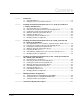
CONTENTS Chapter 1 Introduction 1.1 Related Publications ........................................................................................ 1-3 1.2 Getting Assistance from Reliance Electric....................................................... 1-3 Chapter 2 Installing the Field Current Regulator Kit on 1.5 - 30 HP @ 230 VAC and 3 - 60 HP @ 460 VAC Drives 2.1 Opening the Drive Cover and Carrier .............................................................. 2-1 2.
II FlexPak 3000 Field Current Regulator Installation Instructions
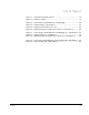
List of Figures Figure 1.1 – Field Current Regulator Board.............................................................. 1-2 Figure 1.2 – Cable Assemblies................................................................................. 1-2 Figure 2.1 – Removing the Standard/Enhanced Field Supply.................................. 2-4 Figure 2.2 – Cable Routing (3 - 60 HP Drives) ......................................................... 2-5 Figure 2.3 – Regulator Board Cable Connectors........................
IV FlexPak 3000 Field Current Regulator Installation Instructions
List of Tables Table 1.1 – Verifying the Field Current Regulator Kit Matches the Drive ................. 1-1 Table 1.2 – Field Current Regulator Kit Contents.....................................................
VI FlexPak 3000 Field Current Regulator Installation Instructions
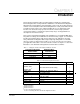
CHAPTER 1 Introduction This instruction manual describes how to install and configure the optional Field Current Regulator kits used by FlexPak™ 3000 drives. The Field Current Regulator, which includes a field regulator and a field supply, can be used only in drives that have software version 3.00 (REGULATOR SW VERSION parameter = 3.00) or later. When the kit is installed, a field control loop is enabled, allowing the user to adjust field control functions.
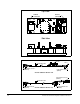
Top View FLD P6 Connector FLD P3 Connector Side View Figure 1.1 – Field Current Regulator Board 4-pin Square Connector (FLD P3) PIN-1 FLD P6 REG P25 Part Number Label 12-pin PCB Connector (REG P25) 10-pin PCB Connector (FLD P6) FlexPak 3000 P/N 707973-12R 4-pin Square Connector (FLD P3) Part Number Label 12-pin PCB Connector (REG P25) FLD P6 REG P25 PIN-1 FlexPak 3000 P/N 707973-12S 10-pin PCB Connector (FLD P6) Figure 1.
1.1 Related Publications Refer to the following related publications as necessary for more information: • D2-3404 • D2-3405 1.2 FlexPak 3000 DC Drive Hardware Reference Manual FlexPak 3000 Digital DC Drive Software Reference Manual Getting Assistance from Reliance Electric If you have any questions or problems with the products described in this instruction manual, contact your local Reliance Electric sales office. For technical assistance, call 1-800-726-8112.
1-4 FlexPak 3000 Field Current Regulator Installation Instructions
CHAPTER 2 Installing the Field Current Regulator Kit on 1.5 - 30 HP @ 230 VAC and 3 - 60 HP @ 460 VAC Drives ! ATTENTION: Only qualified personnel familiar with the construction and operation of this equipment and the hazards involved should install, adjust, operate, and/or service this equipment. Read and understand this instruction manual in its entirety before proceeding. Failure to observe this precaution could result in severe bodily injury or loss of life.
2.1 Opening the Drive Cover and Carrier ! ATTENTION: The drive contains ESD- (Electrostatic Discharge) sensitive parts and assemblies. Static control precautions are required when installing, testing, servicing, or repairing the drive. Erratic machine operation and damage to, or destruction of, equipment can result if this procedure is not followed. Failure to observe this precaution can result in bodily injury. Step 1. Turn off, lockout, and tag power to the drive. Step 2.
2.4 Wiring the Field Current Regulator Board Step 1. The Operator Interface Module (OIM) or Drive Configuration Module (DCM) must be removed to provide access to the Regulator board. Remove the screws that hold the OIM or DCM to the carrier, and remove the OIM/DCM. Step 2. Remove the three screws that hold the Regulator board in place, and slide the Regulator board slightly to the right. Step 3.
Power I/F Board P4 Connector FlexPak Wire Harness Carrier Standard or Enhanced Field Supply Figure 2.
Front View Side View Field Supply Attaching Screws (Qty 4) FlexPak Wire Harness Field Current Regulator Carrier Fan Field Current Regulator Cable Assembly Field Current Regulator Cable Assembly Figure 2.2 – Cable Routing (3 - 60 HP Drives)) J25 Connector J7 Connector J6 Connector J5 Connector Figure 2.3 – Regulator Board Cable Connectors Installing the Field Current Regulator Kit on 1.
600V 25A Figure 2.
CHAPTER 3 Installing the Field Current Regulator Kit on 40 - 75 HP @ 230 VAC and 75 - 150 HP @ 460 VAC Drives ! ATTENTION: Only qualified personnel familiar with the construction and operation of this equipment and the hazards involved should install, adjust, operate, and/or service this equipment. Read and understand this instruction manual in its entirety before proceeding. Failure to observe this precaution could result in severe bodily injury or loss of life.
3.1 Opening the Drive Cover and Carrier, and Removing the AC Disconnect ! ATTENTION: The drive contains ESD- (Electrostatic Discharge) sensitive parts and assemblies. Static control precautions are required when installing, testing, servicing, or repairing the drive. Erratic machine operation and damage to, or destruction of, equipment can result if this procedure is not followed. Failure to observe this precaution can result in bodily injury. Step 1. Turn off, lockout, and tag power to the drive.
Step 2. Connect the drive’s wire harness connectors labeled 581, 582, 583, F2/35 and F1/37 to the corresponding terminals on the Field Current Regulator board. See figure 1.1 for the location of the terminals. Step 3. Attach the Field Current Regulator cable assembly (P/N 707973-12S) FLD P6 and FLD P3 connectors to the corresponding terminals on the Field Current Regulator. See figure 1.1. Step 4.
3.6 Reinstalling the Auxiliary Chassis Cover, Carrier and Drive Cover Step 1. Insert the tabs on the left side of the auxiliary chassis cover into the slots on the right side of the drive’s motor terminal panel. Step 2. Align the auxiliary chassis cover over the middle screw on the drive’s right side panel and over the top and bottom mounting holes. Step 3. Insert the top and bottom screws into the mounting screw holes and then tighten all three mounting screws (top, bottom, and middle). Step 4.
Motor Terminal Panel Auxiliary Chassis Cover Loosen screws Loosen screws Remove 4 screws Remove top and bottom screws; loosen middle screw Remove top and bottom screws; loosen middle screw Drive with AC Disconnect Drive without AC Disconnect Field Supply Drive with Aux. Chassis Cover Removed Figure 3.
600V 25A 600V 25A Figure 3.
CHAPTER 4 Installing the Field Current Regulator Kit on 100 - 150 HP @ 230 VAC and 200 - 300 HP @ 460 VAC Drives ! ATTENTION: Only qualified personnel familiar with the construction and operation of this equipment and the hazards involved should install, adjust, operate, and/or service this equipment. Read and understand this instruction manual in its entirety before proceeding. Failure to observe this precaution could result in severe bodily injury or loss of life.
4.1 Opening the Cover and Carrier ! ATTENTION: The drive contains ESD- (Electrostatic Discharge) sensitive parts and assemblies. Static control precautions are required when installing, testing, servicing, or repairing the drive. Erratic machine operation and damage to, or destruction of, equipment can result if this procedure is not followed. Failure to observe this precaution can result in bodily injury. Step 1. Turn off, lockout, and tag power to the drive. Step 2.
Step 5. Working from the inside of the bottom of the drive, align the Field Current Regulator board’s mounting holes with the mounting holes on the drive’s right side panel. See figure 4.2. Step 6. Working from the outside of the drive, insert one of the mounting screws (removed in step 1) through one of the mounting holes on the drive’s right side panel and into the corresponding mounting hole on the Field Current Regulator board. Tighten the screw to hold the board in place. Step 7.
4.8 Modifying the Drive Configuration Go to chapter 5 for information on setting parameters for the Field Current Regulator kit. Enhanced Field Supply Board Figure 4.1 – Removing the Standard/Enhanced Field Supply (200 - 300 HP Drives) Control Harness Field Current Regulator Cable Figure 4.
Installing the Field Current Regulator Kit on 100 - 150 HP @ 230 VAC and 200 - 300 HP @ 460 VAC Drives 4-5
4-6 FlexPak 3000 Field Current Regulator Installation Instructions
CHAPTER 5 Modifying the Drive Configuration Before you can use the Field Current Regulator kit, you must set the parameters listed below in the FlexPak 3000 drive. These parameters are described in sections 5.1 and 5.2. • Parameter 510 (MOTOR HOT FLD AMPS) • Parameter 511 (FIELD ECONOMY REF) In addition, the input parameters listed below may need to be adjusted in order to tune the field control loop. Refer to your drive’s instruction manual for a complete description of these parameters.
If you are installing and setting up the Field Current Regulator kit after you have already set up the drive, you do not need to rerun the quick start procedure. Simply access the parameters and set the values as described in sections 5.1 and 5.2. 5.1 Setting Parameter 510 (MOTOR HOT FLD AMPS) When the drive is first powered up after installing the Field Current Regulator, the Field Current Regulator will operate in a fixed voltage mode until a valid value is entered for MOTOR HOT FLD AMPS.
Step 17. Turn on power to the drive. Step 18. Access the Fault menu by pressing the FAULT key until FAULT appears on the OIM directly above the FAULT key. Step 19. Select Clear Fault Log and Reset Faults, and then press ENTER. The fault log will be cleared and all drive faults will be reset. If you have an OIM, you are done with setting parameter 510. Go to section 5.1 to set parameter 511 (FIELD ECONOMY REF).
5.2 Setting Parameter 511 (FIELD ECONOMY REF) ! ATTENTION: Improper setting of the field economy ref parameter can cause a motor overvoltage condition. Set the MOTOR HOT FLD AMPS parameter to the motor’s nameplate value. Make sure the FIELD ECONOMY REF parameter and/or FIELD REF parameter (P.513) are above the FIELD LOSS THRESHOLD parameter (P.512). Failure to observe this precaution could result in bodily injury and damage to the equipment.
5.3 Tuning the Field Current Regulator Important: Please review Appendix A for a complete description of the functions of the field current regulator prior to proceeding with manual tuning. In order to provide proper and responsive field current control the user may be required to modify the tuning parameters to meet the needs of the application. Adjustment of the field regulator tuning may be required to properly clamp and regulate the armature voltage at or above base speed motor operation.
Typically, increasing P514 and P515 will increase the field weakening controller response. Decreasing the value of P514 and P515 will slow down the field weakening controller response. After tuning the field regulator, verify that the proper field current regulation and armature voltage clamping occurs under all operating conditions. If the motor is to be operated in the extended speed range, the user may be required to adjust the parameters that relate to field weakening control P518, P519 & P520.
APPENDIX A Field Current Regulator Description Description of the Field Control Loop The FlexPak 3000 version 3 regulator will detect the presence of the Field Current Regulator kit at power-up. The output parameter FLD CURRENT REGULATOR indicates whether or not the Field Current Regulator kit is in-stalled. When the Field Current Regulator kit is installed, the field current control loop operates and drive parameters ENHANCED FLD VOLT ADJ and J21 FLD SUPPLY JUMPER are ignored.
Both field loop regulators contain proportional plus integral (PI) control. There is no user-configurable low limit parameter associated with these PI blocks. The low limit is always fixed at zero. The high limit (FIELD DELTA HI LIM) is user-configurable up to 180 degrees, allowing full-on field voltage of 207 VDC @ 230 VAC and 414 VDC @ 460 VAC. To regulate greater field voltages, a step-up transformer must be used to supply the AC side of the Field Current Regulator.
Field Current Regulator Description Field Current Regulator FIELD PI PROP GAIN FIELD PI LEAD FREQ MOTOR HOT FLD AMPS KP (FIELD ECONOMY ACTIVE) HI WLD (FIELD DELTA) (FIELD REFERENCE) OFF FIELD REF REGISTER + - ON LO Field Phase Firing Logic PI LO FIELD REGULATOR SUPPLY HI GAIN MOTOR HOT FLD AMPS MUL DIV 100 (FIELD FEEDBACK) FIELD ECONOMY REF Figure A.
Figure A.2 – Drive Operation Over the Constant Torque and Constant Power Range Field Current Feedback Scaling There are three Field Current Regulator ratings: 4 amps, 10 amps, and 15 amps. The Regulator board hardware provides three different gains for the field current feedback signal: 1, 2, and 5. The user must enter the motor nameplate value for rated field amps (MOTOR HOT FLD AMPS) to properly scale the feedback signal.
Field Loss When the Field Current Regulator is operating in fixed voltage mode, a field current loss fault will be generated only when there is a complete loss of field current. When the Field Current Regulator is regulating field current (that is, not in fixed voltage mode), a field current loss fault will be generated when the field current drops below the user-set FIELD LOSS THRESHOLD. The same field feedback signal used by the Field Current Regulator is used by the field loss detection circuit.
U.S. Drives Technical Support Tel: (1) 262.512.8176, Fax: (1) 262.512.2222, Email: support@drives.ra.rockwell.com, Online: www.ab.com/support/abdrives Trademarks not belonging to Rockwell Automation are property of their respective companies. Publication D2-3336-2 – December 2001 Copyright © 2001 Rockwell Automation, Inc. All Rights Reserved. Printed in USA.