FlexPak 3000 Digital DC Drive Hardware Reference, Installation and Troubleshooting Version 4.
The information in this manual is subject to change without notice. Throughout this manual, the following notes are used to alert you to safety considerations: ! ATTENTION: Identifies information about practices or circumstances that can lead to personal injury or death, property damage, or economic loss. Important: Identifies information that is critical for successful application and understanding of the product.
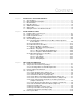
CONTENTS Contents Chapter 1 Introduction to the FlexPak 3000 Drive 1.1 Store the Drive................................................................................................. 1-1 1.2 Drive Identification Nameplate......................................................................... 1-1 1.3 Model Numbers ............................................................................................... 1-2 1.4 Drive Description .....................................................................
3.6 3.7 3.8 3.9 Verify the Correct Direction of Motor Rotation ...............................................3-10 Determine the DC Tachometer Lead Polarity ................................................3-11 Make Tachometer and Armature Feedback Zero Adjustments .....................3-11 Make Final Adjustments.................................................................................3-12 Chapter 4 Troubleshooting/Diagnostics 4.1 Check for Wiring Errors.............................................
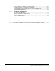
List of Figures Figure 1.1 – Sample FlexPak 3000 Nameplates ...................................................... 1-1 Figure 1.2 – Model Number Structure ...................................................................... 1-2 Figure 1.3 – FlexPak 3000 Functional Block Diagram.............................................. 1-3 Figure 2.1 – Enclosure Mounting Minimum Clearance Distances ............................ 2-1 Figure 2.2 – Drive Mounting Dimensions (1.
Figure 2.25 – Location of Regulator Board Terminal Strip......................................2-31 Figure 3.1 – Control Transformer Locations and Settings (380/415 VAC Drives) ....3-2 Figure 3.2 – Control Transformer Settings (230/460 VAC) .......................................3-3 Figure 3.3 – Regulator Board Jumpers .....................................................................3-6 Figure 3.4 – AUTO REF Jumpers (J12 and J10) ......................................................
List of Tables Table 1.1 – Drive Modification Kits ........................................................................... 1-4 Table 2.1 – Chassis Ground Torgue Requirements ............................................... 2-10 Table 2.2 – Recommended Lug Model and Part Numbers .................................... 2-17 Table 2.3 – AC Line Torque Recommendations..................................................... 2-19 Table 2.4 – Armature Terminal Torqure Recommendations .................................
VI FlexPak 3000 DC Drive Hardware Reference Version 4.
CHAPTER 1 Introduction to the FlexPak 3000 Drive The products described in this instruction manual are manufactured by Reliance Electric Industrial Company. 1.1 Store the Drive After receipt inspection, repack the drive in its original shipping container until ready for installation. To ensure satisfactory operation at startup and to maintain warranty coverage, store the drive as follows: 1.2 • In its original shipping container in a clean, dry, safe place.
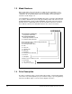
1.3 Model Numbers Drive specific data, such as horsepower (or output current), regenerative or nonregenerative type, line voltage, chassis or enclosure type, software version and UL certification, can be determined by the drive model number. The model number structure is shown in figure 1.2.
The drive employs a wireless construction and uses a keypad for drive setup, including parameter adjustments and unit selection, monitoring, and diagnostics. Multiple language capability in English, French, German, Spanish, Italian and ‘Numeric Code' is available. Reference, feedback, and metering signals can be interfaced to the drive. The drive can be controlled locally by the Operator Interface Module (OIM) keypad or remotely by using the terminals at the regulator board terminal strip.
1.6 Optional Kits Reliance offers modification kits that broaden the application range of the drive. A summary of these kits is presented in table 1.1. Not all kits can be used with all drive model numbers. Refer to the Standard Drives and Control Products catalog (D-406) for more information. Table 1.1 – Drive Modification Kits Name Model Number Description I/M Number 115 VAC Control Interface Converts customer-supplied 115 VAC signals to 24 VDC for operating a FlexPak 3000.
Table 1.1 – Drive Modification Kits Name Description Model Number I/M Number Dynamic Braking Kit Provides the hardware, including braking grids, needed to provide dynamic braking on stop. 908FK, 909FK, 912FK, and 913FK series D2-3313 or D2-3374 Enhanced Field Supply Kit Provides electronic field trim, field economy, and the ability to supply 240V field voltage and other special voltages. This kit replaces the standard field supply.
1-6 FlexPak 3000 DC Drive Hardware Reference Version 4.
CHAPTER 2 Install and Wire the Drive 2.1 Install the Drive - Panel Layout Minimum clearances must be maintained when the drive is mounted within a cabinet as shown in figure 2.1. This allows adequate ventilation for the drive. Regardless of these placement guidelines, the user is responsible for ensuring that the drive's ambient temperature specification. See appendix A for more information. Install the drive(s) in the cabinet. Refer to figures 2.2 through 2.7 for mounting dimensions. Figure 2.
Figure 2.2 – Drive Mounting Dimensions (1.5 to 30 HP @ 230 VAC / 3 to 60 HP @ 460 VAC / 7 to 110 Amp Rated Output) 2-2 FlexPak 3000 DC Drive Hardware Reference Version 4.
Figure 2.
Figure 2.4 – Drive Mounting Dimensions (100 to 150 HP @ 230 VAC / 200 to 300 HP @ 460 VAC) 2-4 FlexPak 3000 DC Drive Hardware Reference Version 4.
Figure 2.
Figure 2.6 – Integrator Drive Mounting Dimensions (1.5 to 30 HP @ 230 VAC / 3 to 60 HP @ 460 VAC 2-6 FlexPak 3000 DC Drive Hardware Reference Version 4.
Figure 2.
2.2 Install a Transformer ! ATTENTION:If an input transformer is installed ahead of the drive, a power disconnecting device must be installed between the power line and the primary of the transformer. If this power disconnecting device is a circuit breaker, the circuit breaker trip rating must be coordinated with the inrush current (10 to 12 times full-load current) of the input transformer.
2.4 Install the Motor Step 1. Verify that the motor is the appropriate rating to use with the drive. Step 2. Install the DC motor in accordance with its installation instructions. Step 3. Make sure that coupled applications have proper shaft alignment with the driven machine or that belted applications have proper sheave/belt alignment to minimize unnecessary motor loading. Step 4. If the motor is accessible while it is running, install a protective guard around all exposed rotating parts. Step 5.
Step 4. Connect a suitable equipment grounding conductor to the motor frame, the transformer enclosure if used, and the drive enclosure. Run this conductor unbroken to the grounding electrode. Step 5. Connect the GND (green/ground) wire brought in with the incoming AC power line to the drive ground point. Step 6. Tighten chassis ground connections per table 2.1. Table 2.1 – Chassis Ground Torgue Requirements Hardware Size 2-10 Tightening Torque M5 18 lb/in (2 Nm) M6 33 lb/in (3.
Figure 2.8 – Drive Control and Power Ground Point Locations (1.
Figure 2.9 – Drive Control and Power Ground Point Locations (40 to 75 HP @ 230 VAC / 75 to 150 HP @ 460 VAC / 265 Amp Rated Output) 2-12 FlexPak 3000 DC Drive Hardware Reference Version 4.
Figure 2.
Figure 2.11 – Drive Control and Power Ground Point Locations (400 to 600 HP @ 460 VAC) 2-14 FlexPak 3000 DC Drive Hardware Reference Version 4.
Figure 2.12 – Integrator Drive Control and Power Ground Point Locations (1.
Figure 2.13 – Integrator Drive Control and Power Ground Point Locations (40 to 75 HP @ 230 VAC / 75 to 150 HP @ 460 VAC) 2-16 FlexPak 3000 DC Drive Hardware Reference Version 4.
2.5.2 Recommended Lugs The following describes how to interpret lug model numbers used in grounding the drive. Refer to table 2.2 for a list of recommended lug model and part numbers.
2.5.3 Wire AC Power to the Drive ! ATTENTION:The user is responsible for conforming to the National Electric Code (NEC/CEC) and all other applicable local codes. Wiring practices, grounding, disconnects, and overcurrent protection are of particular importance. Size and install wiring in conformance with the NEC/CEC and all other applicable codes. Failure to observe this precaution could result in severe bodily injury or loss of life.
Table 2.3 – AC Line Torque Recommendations AC Input Horsepower 1.5 2 3 5 7.5 10 15 20 25 30 40 50 60 75 100 125 150 200 250 300 400 500 600 Rated Output Amps 7A 29A 55A 110A 265A 230 VAC 55 lb-in (6.2 Nm) 55 lb-in (6.2 Nm) 55 lb-in (6.2 Nm) 55 lb-in (6.2 Nm) 55 lb-in (6.2 Nm) 55 lb-in (6.2 Nm) 120 lb-in (13.6 Nm) 120 lb-in (13.6 Nm) 120 lb-in (13.6 Nm) 120 lb-in (13.
Figure 2.14 – AC Line Connection Location (1.5 to 30 HP @ 230 VAC 3 to 60 HP @ 460 VAC / 7-110 Amp Rated Output) Figure 2.15 – AC Line Connection Location (40 to 75 HP @ 230 VAC /75 to 150 HP @ 460 VAC / 265 Amp Rated Output) 2-20 FlexPak 3000 DC Drive Hardware Reference Version 4.
AC LINE CONNECTION AC LINE CONNECTION Shown Without Optional AC Line Disconnect Shown With Optional AC Line Disconnect Figure 2.16 – AC Line Connection Locations (100 to 150 HP @ 230 VAC / 200 to 300 HP @ 460 VAC) Figure 2.
2.5.4 Wire the DC Motor to the Drive Step 1. Size the motor armature circuit conductors for the specific drive rating (see Appendix A) and according to applicable codes. Use only copper wire rated 60/70°C or higher. Step 2. Locate the DC motor armature and field supply leads on the drive. Refer to figure 2.18 to 2.21. Step 3. Connect the DC motor armature leads and the shunt field supply leads to the drive. See figure 2.22. Step 4. Tighten armature connections per table 2.4.
Figure 2.
Figure 2.20 – DC Motor Field and Armature Connection Locations (100 to 150 HP @ 230 VAC / 200 to 300 HP @ 460 VAC) 2-24 FlexPak 3000 DC Drive Hardware Reference Version 4.
Figure 2.
Figure 2.22 – DC Motor Connections (CCW Rotation Facing Commutator End Shown) 2-26 FlexPak 3000 DC Drive Hardware Reference Version 4.
Table 2.4 – Armature Terminal Torqure Recommendations Armature Terminal Torque 230 VAC Input 460 VAC Input Horsepower Rated Drives 1.5 2 3 5 7.5 10 15 20 25 30 40 50 60 75 100 125 150 200 250 300 400 500 600 8-9 lb-in (.9-1.0 Nm) 8-9 lb-in (.9-1.0 Nm) 8-9 lb-in (.9-1.0 Nm) 8-9 lb-in (.9-1.0 Nm) 55 lb-in (6.2 Nm) 55 lb-in (6.2 Nm) 55 lb-in (6.2 Nm) 150 lb-in (16.9 Nm) 150 lb-in (16.9 Nm) 150 lb-in (16.
2.5.5 Wire the Stop Input ! ATTENTION:The user must provide an external, hardwired emergency stop circuit outside of the drive circuitry. This circuit must disable the system in case of improper operation. Uncontrolled machine operation may result if this procedure is not followed. Failure to observe this precaution could result in bodily injury.
2.5.5.1 Wire the COAST/STOP Digital Input The user must provide an external operator-accessible coast/stop pushbutton at terminals 7 and 8 on the Regulator board to disable the machine in case of improper operation. Uncontrolled machine operation might result if this is not done. The customer interlock is a software-based stop function unless wired in series with the coast/stop input. Any safety-related stops must be wired through the coast/stop input.
Optional Jog with Optional Jog selector switch maintained contact Start/Stop 1 1 Start Stop 2 Run 2 3 Run 4 Jog Run Jog Jog 3 4 Figure 2.24 – Sample Regulator Board Terminal Strip Connection Diagram 2-30 FlexPak 3000 DC Drive Hardware Reference Version 4.
RS-232 Connector Figure 2.
2.5.6 Wire Optional Devices to the Drive ! ATTENTION:Do not route signal wiring with power wiring in the same conduit. This might cause interference with drive operation. Route signal wiring and power wiring in separate conduits. Failure to observe this precaution could result in damage to, or destruction of, the equipment. Refer to figures 2.24 and 2.25 and table 2.5 when wiring optional devices to the drive. Size and install all wiring in accordance with the NEC and all other applicable local codes.
2.5.6.1 Logic Inputs ! ATTENTION:Connecting an external power source to any of the +24 volt connections (terminals 1, 7, 11, and 14) on the Regulator board terminal strip will damage the drive. DO NOT connect the external power source on the +24 volt connections on the Regulator board terminal strip. Failure to observe this precaution could result in damage to, or destruction of, the equipment.
2-34 FlexPak 3000 DC Drive Hardware Reference Version 4.
CHAPTER 3 Drive Setup and Adjustment ! 3.1 ATTENTION: Only qualified electrical personnel familiar with the construction of this equipment and the hazards involved should install, adjust, operate, and/or service this equipment. Read and understand this section in its entirety before proceeding. Failure to observe this precaution could result in severe bodily injury or loss of life. Perform a Power Off Inspection Inspect the drive and modification kits for possible physical damage or improper connections.
Figure 3.1 – Control Transformer Locations and Settings (380/415 VAC Drives) 3.2.2 Converting a Drive for 230 VAC Input Power ! ATTENTION: 230/460 VAC-rated FlexPak 3000 drives can be configured for either 230 VAC or 460 VAC input power. Before input power is applied to the drive, verify that the control transformer taps are set to match the input power. Failure to observe this precaution could result in damage to, or destruction of, the equipment.
Step 4. Re-connect power to the drive. Step 5. Through the OIM, access the NOMINAL AC LINE VOLTS parameter (P.037). Set the value to 230. Figure 3.2 – Control Transformer Settings (230/460 VAC) 3.3 Perform a Motor Ground Check ! ATTENTION: A megohmmeter can be used for this motor ground check, but all conductors between the motor and the drive must be disconnected. The megohmmeter’s high voltage can damage the drive’s electronic circuits.
Verify that there is no path to ground in either the DC motor armature circuit, the shunt field circuit or the thermostat circuit. Connect one lead of an ohmmeter to the motor frame and the other lead to the two armature leads, then to the two field leads and to the two thermostat leads. If a reading of less than 100,000 ohms is observed, a ground condition exists and MUST be corrected before power is applied. 3.
Table 3.1 – Jumper Settings DEFAULT SETTING JUMPER J15 (REGULATOR TYPE) SPEED J16 (OIM PROGRAM) ENABLE J20 (FIELD LOSS DETECT) ENABLE J21 (FIELD SUPPLY JUMPER) B-C J19 (MANUAL REF) POT J14 (TACH V RANGE) 62 J11 (TACH V SCALE) 16 J10 (AUTO REF) VOLTS J12 (AUTO REF) VOLTS J18 (ARM I FB RB) Position 4 J26 (not used) J27 (SPARE 1) (not used) J28 (FILTER SELECT) (not used) J29 (SPARE 2) (not used) J30 (POWER UNIT) LOW FINAL SETTING Jxx is not used.
Figure 3.3 – Regulator Board Jumpers 3.4.2 Setting Program Protection (Jumper J16) The OIM program jumper (J16) determines whether or not parameter changes can be made through the keypad (OIM). Only programming options are affected by the setting of this jumper. The OIM drive control keys (such as RUN and JOG) and the manual speed reference are not affected. To allow keypad parameter changes, place the jumper on pins 1 and 2 (ENABLE).
3.4.3 Set Field Loss Detection (Jumper J20) The FIELD LOSS DETECT jumper (J20) determines whether or not a fault is generated when a field loss occurs. Important: Jumper J20 is ignored if the Field Current Regulator kit is installed. Therefore, placing J20 in the DISABLE position will not disable field loss detection. See I/M D2-3336 for more information on the Field Current Regulator.
To use the +10V power supply for the manual reference potentiometer, place the jumper on pins 2 and 3 (POT). The supply at terminal 16 of the regulator board terminal strip is used. To use an external +10 V source, place the jumper on pins 1 and 2 (EXT). The external reference is connected at terminals 17 and 18 of the regulator board terminal strip. Note that this input can be used as a trim on the auto mode speed reference by setting the jumper on pins 1 and 2 (EXT). 3.4.
3.4.7 Set the Analog Auto Mode Reference (Jumpers J12 and J10) The AUTOREF jumpers (J12 and J10) select the type of analog auto reference to be used when the AUTO mode is selected. J12 selects the type of signal (voltage or milliamps). J10 selects the range. See figure 3.4 for the jumper settings. Figure 3.4 – AUTO REF Jumpers (J12 and J10) 3.4.8 Scale the Armature Current Feedback (Jumper 18) ! ATTENTION: The drive will not operate at the correct speed if this jumper is not set to the correct position.
3.4.13 Inspect the Power Unit Jumper (J30) ! ATTENTION: The drive can operate at excessive armature voltage and speed if J30 is improperly set to the LOW position when it should be set to HI. Important: An optional Power Interface module, for drives which are powered from a 690 Vrms AC line, is available only on drives manufactured by Reliance Electric Dierikon, Switzerland. In order to operate properly with this new power I/F module, a hardware jumper (J30) was added to the regulator board.
Step 4. After power-up, select ARMATURE VOLT for FEEDBACK SELECT by taking the following path from the main menu to access this parameter: Speed/Voltage Loop (SPD) Speed/Voltage Loop (SPD) Feedback Refer to the FlexPak 3000 Software Reference manual for more information on changing parameter values. Step 5. Initiate a JOG command to verify that the motor is rotating in the desired direction for the Forward command. Step 6.
! ATTENTION: The incorrect setting of the parameters described below can cause an overspeed condition. These parameters must be set by a qualified person who understands the significance of setting them accurately. Verify that the value of these parameters is accurate for your application. Failure to observe this precaution could result in bodily injury. Step 1. Stop the drive. Step 2. Check the value of the output parameter ARMATURE VOLTAGE (P.289). If the value is 0: Go to step 5.
CHAPTER 4 Troubleshooting/Diagnostics ! ATTENTION: Only qualified electrical personnel familiar with the construction of this equipment and the hazards involved should install, adjust, operate, and/or service this equipment. Read and understand this section in its entirety before proceeding. Failure to observe this precaution could result in severe bodily injury or loss of life. ATTENTION: This equipment is at line voltage when AC power is connected.
4.3 Verify DC Motor Connections ! ATTENTION: A megohmmeter can be used for this motor ground check, but all conductors between the motor and the drive must be disconnected. The megohmmeter’s high voltage can damage the drive’s electronic circuits. Disconnect all conductors between the motor and the drive before using a megohmmeter for this motor ground check. Failure to observe this precaution could result in damage to, or destruction of, the equipment. Verify that all DC motor connections are correct.
4.5 Check the Regulator LED Status Two LEDs on the Regulator board indicate the operating status of the Regulator board. The cover on the OIM must be removed to observe these LEDs. Check these LEDs when the OIM is not communicating with the regulator. Typically, there will be no fault indication on the display when the OIM is not communicating with the Regulator board. If a fault can be displayed, the fault would be OIM COMMUNICATIONS TIMEOUT (F00011). The two LEDS are labeled CPU OK and OIM COMM OK.
4-4 FlexPak 3000 DC Drive Hardware Reference Version 4.
CHAPTER 5 Replacement Parts ! ATTENTION: Only qualified electrical personnel familiar with the construction of this equipment and the hazards involved should install, adjust, operate, and/or service this equipment. Read and understand this section in its entirety before proceeding. Failure to observe this precaution could result in severe bodily injury or loss of life ATTENTION: .This equipment is at line voltage when AC power is connected.
5-2 FlexPak 3000 DC Drive Hardware Reference Version 4.
APPENDIX A Technical Specifications Table A.1 – Voltage and Current Ratings Input Voltage and Frequency Ratings Nominal Voltage 230 VAC ± 10% or 460 VAC ± 10% (horsepowerrated drives) 385 VAC ± 10% or 415 VAC ± 10% (current-rated drives) Nominal Line Frequency 50 Hz or 60 Hz Frequency Variation 2 cycles of nominal AC Line Fault Capacity Maximum Symmetrical Fault Current See table A.6 AC Line KVA AC Line Distribution Capacity Maximum of 3 drives per transformer Minimum Source KVA See table A.
Table A.2 – Service Conditions Service Factor 1.0 continuous Overload Capacity 150% of full load for 1 minute Motor Overload Function Drive uses an internal inverse time thermal overload based on motor amp measurement and full load motor rated amps parameter entry.
Table A.6 – Power Ratings1 (230/460 VAC) HP Full Load Rated RMS AC Line Current (Amperes) Full Load Rated DC Armature Current (Amperes) Rated Field Current (Amperes) Maximum Symmetrical AC Fault Current (Amperes) Min. Source KVA 230 VAC 460 VAC 240 VDC 500 VDC 150 VDC 300 VDC 230 VAC 460 VAC 1.5 10 — 7 — 10 — 5000 — 4 2 11 — 9 — 10 — 5000 — 5 3 13 10 12 6 10 10 5000 5000 6 5 19 12 20 10 10 10 5000 5000 7.5 7.
Table A.7 – Power Ratings1 (380/415 VAC) Unit Type Input Voltage (VAC) Full Load Rated RMS AC Line Current (Amperes) Full Load Rated DC Armature Current (Amperes) Rated Field Current (Amperes) Maximum Symmetrical AC Fault Current (Amperes) Min.
Table A.10 – Analog Inputs Manual Mode Reference Potentiometer External Voltage Source 5 KΩ minimum ±10 VDC (when used for analog trim reference) 0 to 10 VDC (when used for manual mode speed reference) Automatic Mode Voltage Reference Current Reference ±10 VDC 4 to 20 mA or 10 to 50 mA Analog Tachometer Feedback Tach Voltage at Top Speed 10 to 250 VDC Table A.
A-6 FlexPak 3000 DC Drive Hardware Reference Version 4.
APPENDIX B Compliance with European Union Electromagnetic Compatibility Standards This appendix provides information on installing FlexPak 3000 drives for compliance with European Union Electromagnetic Compatibility (EMC) Standards. It covers: • requirements for standards compliance. • guidelines on installing the AC mains filter and inductor. • instructions on how the drive must be installed, wired, and grounded for compliance.
B.2 Selecting the Equipment In addition to the drive, you will need the following to install the drive for CE compliance: • AC mains filter • AC mains inductor • Electrical cabinet with back mounting panel B.2.1 Selecting a Mounting Panel and Electrical Cabinet The FlexPak 3000 drive, AC mains filter, AC mains inductor, and any other electronic or electrical equipment must be mounted in an electrical cabinet.
Table B.1 – AC Mains Filter Model Numbers for 1.5 to 150 HP @ 230 VAC FlexPak 3000 Drives HP Rating AC Full Load Amps Minimum Inductance (in microhenries (µH)) AC Mains Filter Model Number AC Mains Inductor 1.5 10 850 3DF4353 608895-63H 2 11 770 3DF4353 608895-63H 3 13 650 3DF4353 608895-63K 5 19 470 3DF4354 608895-63K 7.
Table B.2 – AC Mains Filter Model Numbers for 3 to 300 HP @ 460 VAC FlexPak 3000 Drives HP Rating AC Full Load Amps Minimum Inductance (in microhenries (µH)) AC Mains Filter Model Number AC Mains Inductor 3 10 1680 3DF4353 608895-63H 5 12 1400 3DF4353 608895-63H 7.
B.3 Mounting the Equipment Mount all electronic and electromagnetic components, including the drive and the mains filter, firmly to the base mounting panel. The mounting panel must have good conductivity, as described in section B.2.1, Selecting a Mounting Panel and Electrical Cabinet. These sections provide more detail on mounting the drive, AC mains filter, and AC mains inductor. B.3.
L1' L2' L3' E LOAD LINE L1 L2 L3 E LOAD LINE Figure B.2 – 3DF4353 and 3DF4354 Filter Dimensions Figure B.3 – 3DF4355 Filter Dimensions B-6 FlexPak 3000 DC Drive Hardware Reference Version 4.
LOAD LINE Figure B.4 – 3DF4357 Filter Dimensions Figure B.
Figure B.6 – Side Mounting the 3DF4359 Filter in the L Bracket B.3.3 Mounting the AC Mains Inductor Important: Many inductors are coated with varnish. Any varnish on the inductor's mounting area must be removed to ensure conductivity. See the manufacturer's documentation for additional mounting instructions. B-8 FlexPak 3000 DC Drive Hardware Reference Version 4.
B.4 Grounding Requirements Star grounding must be used and must provide traditional product safety grounds, such as high current, low frequency, and high frequency noise control. B.4.1 System Power Ground The common power distribution system found in European countries includes the grounded neutral of the WYE transformer, as shown in figure B.7. Local code determines whether this fourth wire may be used as the system ground.
Figure B.8 – Proper Termination of Screened Cables with a Termination Fitting Figure B.9 – Proper Termination of Screened Cables with a Termination Bracket When using a conduit termination fitting to terminate the screen or rigid conduit, the area around the entry hold must be free of paint and protected from corrosion.
Main Electrical Cabinet Terminate ground wire to ground at both ends Electrical Components, such as remote operator stations and motor. Screened Cable or Conductive Conduit Terminate the screen to ground at both ends Figure B.10 – Ground System and Conduit Screen Termination The minimum cross-sectional area of a copper ground conductor shall be per EN60204-1: Safety of Machinery - Electrical equipment of machines - Part 1: General requirements, section 5.2, Table 1.
Figure B.11 – Dressing Power and Control Wires When the AC power leads must leave the ground plane of the mounting panel to make connection to elevated device terminals, a ground wire should be run with that wire bundle. See figures B.13 and B.14 for typical panel electrical layouts. B.5.3 Wiring the AC Mains Filter The mains filter is connected in series from the AC supply line to the AC mains inductor to the input terminals of the drive. See figure B.12.
The external motor wiring must be run in a screened cable or continuous conductive conduit. The motor shunt field and armature leads can be run together in the same cable. A ground wire must be run that bonds the motor to the system star ground. Refer to figure B.10 for proper connection of the conduit screen and bonding wire. Motor cable length is a major contributor to common mode conducted emissions.
B.5.6.3 Pulse Encoder and AC Tachometer Feedback Kits (Model Numbers 907FK0101 and 907FK0301) The tachometer cables for these kits must be run as screened cable or in a continuous conductive conduit. A ground wire must be run with the tachometer wires and terminated to ground at both ends. The screen or conduit must be terminated at both ends to ground as discussed above and shown in figure B.10. B-14 FlexPak 3000 DC Drive Hardware Reference Version 4.
AC POWER ENTRY V W U PE ELECTRICAL CABINET ENCLOSURE DISCONNECT 181 182 183 F2 F1 A1 A2 AC MAINS FILTER GROUNDING BUS BAR FLEXPAK 3000 DRIVE REGULATOR BOARD TERMINALS TO I/O EXPANSION TERMINALS REGULATOR BOARD CONVENIENCE TERMINALS A1 A2 F1 F2 AC MAINS INDUCTOR I/O EXPANSION BOARD CONVENIENCE TERMINALS GROUNDING BUS BAR DC MOTOR ARMATURE AND FIELD CONDUIT CONTROL CONDUIT BRAIDED STRAP BRAIDED STRAP ENCLOSURE SKIN AND DOOR TO GROUND BAR TACHOMETER CONDUIT Figure B.
AC POWER ENTRY W PE U V DYNAMIC BRAKING EXPANDED METAL RESISTOR ENCLOSURE FUSE DYNAMIC BRAKING CONTACTOR CONT XFMR ENCLOSURE DISCONNECT 181 182 183 F2 F1 A1 A2 AC MAINS FILTER GROUNDING BUS BAR FLEXPAK 3000 DRIVE REGULATOR BOARD TERMINALS REGULATOR BOARD CONVENIENCE TERMINALS A1 A2 F1 F2 AC MAINS INDUCTOR GROUNDING BUS BAR DC MOTOR ARMATURE AND FIELD CONDUIT CONTROL CONDUIT BRAIDED STRAP BRAIDED STRAP FROM ENCLOSURE SKIN AND DOOR TO GROUND BAR TACHOMETER CONDUIT Figure B.
APPENDIX C Recommended Parts for Integrator Drives Table C.1 lists the recommended parts that must be provided by the user and can be mounted separately at the time of installation. These recommended parts or an equivalent are necessary for the proper operation and functionality of the Integrator drive. Section 2.5, General Wiring Practices, details how to electrically connect these recommended parts for proper drive operation. Table C.
Table C.1 – Recommended Parts Part Description Qty Reliance Part Number Rating Inverting Fault Breaker: 1.5 thru 2 HP @ 230 VAC/3 thru 5 HP @ 460 VAC4 1 77801-18DXA Set at A 40A, 600V 3 thru 5 HP @ 230 VAC/7.5 thru 10 HP @ 460 VAC 1 419035-100DSA Set at L 50A, 600V 7.
AFB 188 189 1 2 3 4 5 6 F1 F2 581 582 583 Figure C.1 – Integrator Drive AC Line Connection Locations (1.
Figure C.2 – Integrator Drive AC Line Connection Locations (40 to 75 HP @ 230 VAC / 75 to 150 HP @ 460 VAC) C-4 FlexPak 3000 DC Drive Hardware Reference Version 4.
C.2 Wire Control Power to the Drive Connect the user supplied 115 VAC supply to terminals 188 and 189 of the controller’s power terminal block. This 115 VAC supply must be rated at 150VA minimum for 150 HP @ 460 VAC and be sized to handle the maximum inrush of the drive FN contactor. The 189 terminal may be tied to protective earth ground if required. See figure C.3. P5-5 SEE SHEETS 3, 8 AND 9 FOR DETAILS. P5-6 AC INPUT S6/S6R DC ARMATURE SUPPLY Figure C.
C-6 FlexPak 3000 DC Drive Hardware Reference Version 4.
APPENDIX D Glossary Of Terms altitude: The atmospheric altitude (height above sea level) at which the motor or drive will be operating. armature: The portion of the DC motor that rotates. rated full load current: Armature current in amperes. armature Resistance: Measured in ohms at 25 degrees Celsius (cold). base speed: The speed which a DC motor develops at rated armature voltage and rated field current with rated load applied. Typically nameplate data.
inertial load: A load (flywheel, fan, etc.) which tends to cause the motor shaft to continue to rotate after the power has been removed (stored kinetic energy). If this continued rotation cannot be tolerated, some mechanical or electrical braking means must be applied. This application may require a special motor due to the energy required to accelerate the inertia. Inertia is measured in lb. ft. squared, oz. in. squared, or mkg squared.
service factor (SF): When used on a motor nameplate, a number which indicates how much above the nameplate rating a motor can be loaded without causing serious degradation, (i.e., a 1.15 SF can produce 15% greater torque than a 1.0 SF rating of the same motor). tachometer: Normally used as a rotational sensing device. Tachometers are typically attached to the output shaft of a motor requiring close speed regulation.
D-4 FlexPak 3000 DC Drive Hardware Reference Version 4.
INDEX A C AC line connection location, 1-18 to 1-21 1.
F motor wiring connections, 1-22 to 1-25 mounting, 1-1 EMC compliance requirements, 1-5 mounting dimensions 1.
J P jumper settings, 1-4 to 1-10 analog tach voltage and analog tach scale (J14 and J11), 1-8 armature current feedback (J18), 1-9 enhanced field supply (J21), 1-7 field loss detection (J20), 1-7 filter select (J28), 1-9 manual mode reference (J19), 1-7 power unit (J30), 1-10 program protection (J16), 1-6 regulator type (J15), 1-5 table of settings, 1-5 panel layout, 1-1 phone number, technical assistance, 1-5 power unit jumper (J30), 1-10 program protection jumper (J16), 1-6 R recommended parts list,in
troubleshooting W AC line and power input, 1-1 DC motor connections, 1-2 OIM, 1-3 optional kits, 1-2 Regulator board, 1-3 technical assistance, 1-5 wiring errors, 1-1 Index-4 wiring AC mains filter, 1-12 AC power, 1-18 to 1-19 coast/stop, 1-29 general practices, 1-9 motor connection locations, 1-22 to 1-25 optional devices, 1-32 troubleshooting, 1-1 FlexPak 3000 DC Drive Hardware Reference Version 4.
U.S. Drives Technical Support Tel: (1) 262.512.8176, Fax: (1) 262.512.2222, Email: support@drives.ra.rockwell.com, Online: www.ab.com/support/abdrives Publication D2-3404-2- June 2004 Copyright © 2004 Rockwell Automation, Inc. All Rights Reserved. Printed in USA.