
Manual


III
List of Figures
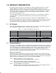
Figure 1.1 Ć 115 VAC Control Option Board 1Ć3.....................................................
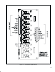
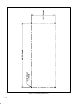
Figure 1.2 Ć Mounting Dimensions 1Ć4.............................................................
Figure 2.1 Ć Recommended 115 VAC Supply Configuration 2Ć2.......................................
Figure 4.1 Ć Control Signal Wiring to a MaxPak III Drive (Example) 4Ć3.................................
Figure A.1 Ć 115 VAC Control Option Board Circuitry AĆ1.............................................
List of Tables
Table 1.1 Ć 115 VAC Control Option Board Parts List 1Ć1.............................................
Table 2.1 Ć AĆC Source Input Connector 2Ć1........................................................
Table 3.1 Ć Control Option Board Wiring to a FlexPak 3000 Drive 3Ć2..................................
Table 4.1 Ć Control Option Board Wiring to a MaxPak III Drive (Example) 4Ć2...........................