
Manual


AĆ1
Appendix A
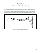
115 VAC Control Option Board Circuitry
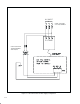
The Control Option Board circuitry consists of ten identical AĆC inputs which are optically coupled to DĆC
source outputs. One of the circuits is shown below in figure A.1. The incoming AĆC is limited by an 8.2K resisĆ
tor and rectified and dropped across a 2.4K resistor in series with 182 ohms. The 182 ohm resistor limits the
turnĆon voltage of the optical isolator. When the optical isolator is turned on, it sinks the input of the Source
Driver, which supplies a DĆC voltage at its output. The Source Driver internally drops a maximum of 2 volts
from the DĆC source voltage (VS).
VS
7.2K
SOURCE DRIVER
8.2K 2W
.
01
AC LO
1uF
182
GND
2.4K 1W
GND
3K
AC HI
DC OUT
7.2K
10K
Figure A.1 Ć 115 VAC Control Option Board Circuitry