
Manual


4Ć2
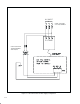
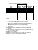
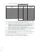
Table 4.1 Ć Control Option Board Wiring to a MaxPak III Drive (Example)
Control Option Board
Control
Device
AĆC Input
Terminal
DĆC Output
Terminal
MaxPak III
Control/Signal
Terminal
RUN ⇒ 2 (IN1) 1 ⇒ 34
STOP ⇒ 3 (IN2) 2 ⇒ 63
JOG ⇒ 4 (IN3) 3 ⇒ 61
REV/FWD ⇒ 5 (IN4) 4 ⇒ 39
NOT USED ⇒ 6 (IN5) 5 ⇒ NOT USED
COAST/STOP ⇒ 8 (IN6) 6 ⇒ 43
INTERLOCK (RUN PERM) ⇒ 9 (IN7) 7 ⇒ EM*
NOT USED ⇒ 10 (IN8) 8 ⇒ NOT USED
NOT USED ⇒ 12 (IN9) 9 ⇒ NOT USED
NOT USED ⇒ 13 (IN10) 10 ⇒ NOT USED
NOTE: 115V HI (L1) is at
11 (+V) ⇒ Any available 24V
()
inputs 1, 7, 11, 14.
12 (GND) ⇒ 66 (IGND)
* Remove wire 46 to EM on MaxPak III terminal.
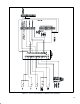
Step 6. Connect the 12Ćpin connector on the cable assembly [Item #4] to the mating DĆC output
connector on the Control Option Board. Refer to figure 1.1 for location.
Step 7. Wire the other end of the cable assembly to the drive's control and signal terminals, using
the pullĆapart" terminal strips on the bottom of the drive. The ends of the wires are
numbered to correspond to the Control Option Board's DĆC Output Terminals, as listed in
table 4.1. Refer to your MaxPak III instruction manual for control and signal terminal
identification. Wire as shown in table 4.1 or to suit your application.
Step 8. Wire the +V terminal (pin 11) on the Control Option Board's DĆC connector to one of the
drive's +24V terminals. Any available +24V terminal (38, 40, 42, etc.) may be used. Refer to
your MaxPak III instruction manual for terminal identification.
Step 9. Wire the Control Option Board's ground (pin 12) to the drive's IGND (terminal 66).
Step 10. Route and secure the cable assembly away from power and 115 VAC control wiring. Loop
any excess cable as required.
Step 11. Remove the lockout and tag. Reconnect power to the drive and the 115 VAC source.
Step 12. Turn on power to the drive and check for proper drive operation.
This completes the installation of the Control Option Board for a MaxPak III drive.