
Manual


3Ć1
3.0 INSTALLING THE CONTROL OPTION BOARD FOR A
FLEXPAK 3000 DRIVE
DANGER
THE DRIVE AND CONTROL OPTION BOARD ARE AT LINE VOLTAGES WHEN CONNECTED TO
SOURCES OF INCOMING AĆC POWER. DISCONNECT, TAG, AND LOCKOUT ALL SOURCES OF AĆC
POWER TO THE DRIVE AND THE CONTROL OPTION BOARD BEFORE PERFORMING THE
FOLLOWING PROCEDURE. FAILURE TO OBSERVE THESE PRECAUTIONS COULD RESULT IN
SEVERE BODILY INJURY OR LOSS OF LIFE.
CAUTION: The user is responsible for conforming with all applicable local, national, and international
codes. Failure to observe this precaution could result in damage to, or destruction of, the equipment.
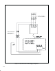
Use the following procedure to install the 115 VAC Control Option Board for use with a FlexPak 3000
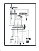
drive. Refer to figures 1.1, 1.2, and 2.1 when performing the installation.
Step 1. Disconnect, tag, and lockout power to the drive and the 115 VAC control voltage supply.
Step 2. Remove the drive cover. For drives with NEMA 1 covers, continue to step 3. For
chassisĆmounted drives, proceed to step 4.
Step 3. For drives up to 150 HP, equipped with NEMA 1 covers, locate the 4 mounting holes in the
back of the bottom end cover. Mount the Control Option Board [Item #1] inside, using the
M4 x 30 Taptite screws [Item #5] and the M4 washers [Item #6]. Proceed to step 5.
NOTE: Older versions of the FlexPak 3000 NEMA 1 drives may not be provided with
mounting holes. If this is the case, continue to step 4 and follow the chassisĆmounted drive
instructions.
Step 4. For chassisĆmounted drives, mount the Control Option Board [Item #1] at an appropriate
panel location, using the four (4) M4 x 30 Taptite screws [Item #5] and the M4 washers
[Item #6]. The board must be located less than 48 inches from the FlexPak 3000 regulator
board terminal strip, ideally just below the drive. Drill the holes for the mounting screws
using the mounting hole pattern shown in figure 1.2.
Step 5. Wire your 115 VAC supply to the 3Ćpin AĆC source input connector [Item #2]. Refer to the
recommendations given in section 2.1 and see table 2.1. Make sure to connect the GND
terminal to earth ground. Attach the AĆC source input connector to the mating connector on
the Control Option Board.
Step 6. If the 115 VAC control supply will not be deĆenergized by opening the drive disconnect,
attach the Danger label [Item #7] to the drive enclosure or cabinet door, ensuring that it is
prominently displayed.
Step 7. Wire your 115 VAC control devices to the Control Option Board's 14Ćpin AĆC input
connector [Item #3]. See figure 1.1 and table 3.1. Connect the 14Ćpin AĆC input connector
to the mating connector on the Control Option Board. The wiring of 115 VAC control
devices to the Control Option Board should mirror that of +24V control devices to your
drive's regulator board. Refer to the section on wiring the drive in your FlexPak 3000
instruction manual.