
Manual


2Ć1
2.0 INSTALLING USERĆSUPPLIED 115 VAC CONTROL
POWER
DANGER
THE DRIVE AND CONTROL OPTION BOARD ARE AT LINE VOLTAGES WHEN CONNECTED TO
SOURCES OF INCOMING AĆC POWER. DISCONNECT, TAG, AND LOCKOUT ALL SOURCES OF AĆC
POWER TO THE DRIVE AND THE CONTROL OPTION BOARD BEFORE PERFORMING THE
FOLLOWING PROCEDURE. FAILURE TO OBSERVE THESE PRECAUTIONS COULD RESULT IN
SEVERE BODILY INJURY OR LOSS OF LIFE.
CAUTION: The user is responsible for conforming with all applicable local, national, and international
codes. Failure to observe this precaution could result in damage to, or destruction of, the equipment.
The user is responsible for providing 115 VAC, 60 Hz. singleĆphase power to the control devices and
the Control Option Board. To ensure safety to personnel, the method described in section 2.1 is
recommended.
2.1 Recommended Method
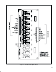
The recommended configuration is shown in figure 2.1. This configuration will guarantee that
opening the drive disconnect will also remove the 115 VAC power from the Control Option Board. All
wiring, fuses, and the stepĆdown transformer must be sized to match the application and the
technical specifications listed in Appendix B. Disconnect, tag, and lockout power to the drive and the
115 VAC control voltage supply before proceeding.
The installation procedure should include the following steps:
D
Connect the control power leads to two phases of the A-C input between the user-supplied A-C
disconnect and the drive. Run these leads to appropriately sized fuses and a step-down
transformer as shown in figure 2.1.
D
Connect the output of the transformer to terminals L1 and L2 on the A-C source input connector
(CON3) as listed in table 2.1.
D
Connect the GND terminal on CON3 to earth ground.
Table 2.1 Ć AĆC Source Input Connector
Terminal
Connection
L1 1
15V HI
L2 1
15V LO
GND
Earth Ground
2.2 Precautions Using Other Methods
If
you choose not to follow the recommended method of providing the 1
15 V
AC control power
,
described in section 2.1, be aware that disconnecting A-C power from the drive will not necessarily
remove the 1
15 V
AC power from the Control Option Board or the control devices. In this case:
D
Attach the Danger label [
Item #7
] to the drive enclosure or cabinet door
, ensuring that it is
prominently displayed.
D
Make sure that both incoming A-C drive power and 1
15 V
AC control power are disconnected,
tagged, and locked out before servicing any component of the drive system.