Installing the 115 VAC Control Option Board M/N 917FK0101 FlexPakr 3000 and MaxPakr III Drives Instruction Manual D2Ć3338
The information in this manual is subject to change without notice. DANGER ONLY QUALIFIED PERSONNEL FAMILIAR WITH THE CONSTRUCTION AND OPERATION OF THIS EQUIPMENT SHOULD INSTALL, ADJUST, OPERATE, AND/OR SERVICE THIS EQUIPMENT. READ AND UNDERSTAND THIS INSTRUCTION MANUAL IN ITS ENTIRETY BEFORE PROCEEDING. FAILURE TO OBSERVE THIS PRECAUTION COULD RESULT IN SEVERE BODILY INJURY OR LOSS OF LIFE. DANGER THE DRIVE AND CONTROL OPTION BOARD ARE AT LINE VOLTAGES WHEN CONNECTED TO SOURCES OF INCOMING AĆC POWER.
Table of Contents 1.0 Product Description . . . . . . . . . . . . . . . . . . . . . . . . . . . . . . . . . . . . . . . . . . . . . . . . . . . . . . . . . . . . . . . . . 1Ć1 1.1 Kit Contents . . . . . . . . . . . . . . . . . . . . . . . . . . . . . . . . . . . . . . . . . . . . . . . . . . . . . . . . . . . . . . . . . . . . . . 1Ć1 1.2 Wiring Guidelines . . . . . . . . . . . . . . . . . . . . . . . . . . . . . . . . . . . . . . . . . . . . . . . . . . . . . . . . . . . . . . . . . 1Ć1 2.
Appendices Appendix A 115 VAC Control Option Board Circuitry . . . . . . . . . . . . . . . . . . . . . . . . . . . . . . . . . . . . . . . . . . . . . . . . . . . AĆ1 Appendix B Technical Specifications . . . . . . . . . . . . . . . . . . . . . . . . . . . . . . . . . . . . . . . . . . . . . . . . . . . . . . . . . . . . . . . . .
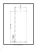
List of Figures Figure 1.1 Ć 115 VAC Control Option Board . . . . . . . . . . . . . . . . . . . . . . . . . . . . . . . . . . . . . . . . . . . . . . . . . . . . . 1Ć3 Figure 1.2 Ć Mounting Dimensions . . . . . . . . . . . . . . . . . . . . . . . . . . . . . . . . . . . . . . . . . . . . . . . . . . . . . . . . . . . . . 1Ć4 Figure 2.1 Ć Recommended 115 VAC Supply Configuration . . . . . . . . . . . . . . . . . . . . . . . . . . . . . . . . . . . . . . . 2Ć2 Figure 4.
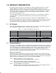
1.0 PRODUCT DESCRIPTION This manual provides instructions for installing the 115 VAC Control Option Board for use with a FlexPakr 3000 drive or MaxPakr III drive. It is intended for qualified electrical personnel. The installation procedure consists of mounting the Control Option Board, wiring user control devices to the board, and wiring the board to the existing control inputs on the FlexPak 3000 drive's regulator board terminal strip or the MaxPak III drive's control and signal terminals.
Level 4 Power Circuits AĆC and DĆC buses up to 1000 V with currents up to 800 A (Class 4S for power greater than 1000 V and/or 800 A.) The installation wiring for these levels must be physically separated to prevent poor system performance as a result of induced noise. Within each level there also may be classes that require additional grouping and separation of installation wiring. These levels and classes are defined in ANSI/IEEE Standard 518, Section 6.4.3.1.
TABLE 4.1 & FIGURE 4.1 Figure 1.
Figure 1.
2.0 INSTALLING USERĆSUPPLIED 115 VAC CONTROL POWER DANGER THE DRIVE AND CONTROL OPTION BOARD ARE AT LINE VOLTAGES WHEN CONNECTED TO SOURCES OF INCOMING AĆC POWER. DISCONNECT, TAG, AND LOCKOUT ALL SOURCES OF AĆC POWER TO THE DRIVE AND THE CONTROL OPTION BOARD BEFORE PERFORMING THE FOLLOWING PROCEDURE. FAILURE TO OBSERVE THESE PRECAUTIONS COULD RESULT IN SEVERE BODILY INJURY OR LOSS OF LIFE. CAUTION: The user is responsible for conforming with all applicable local, national, and international codes.
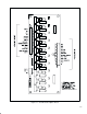
AĆC INPUT USERĆSUPPLIED AĆC DISCONNECT DĆC DRIVE USERĆSUPPLIED TRANSFORMER AND FUSES Figure 2.
3.0 INSTALLING THE CONTROL OPTION BOARD FOR A FLEXPAK 3000 DRIVE DANGER THE DRIVE AND CONTROL OPTION BOARD ARE AT LINE VOLTAGES WHEN CONNECTED TO SOURCES OF INCOMING AĆC POWER. DISCONNECT, TAG, AND LOCKOUT ALL SOURCES OF AĆC POWER TO THE DRIVE AND THE CONTROL OPTION BOARD BEFORE PERFORMING THE FOLLOWING PROCEDURE. FAILURE TO OBSERVE THESE PRECAUTIONS COULD RESULT IN SEVERE BODILY INJURY OR LOSS OF LIFE.
Table 3.
4.0 INSTALLING THE CONTROL OPTION BOARD FOR A MAXPAK III DRIVE DANGER THE DRIVE AND CONTROL OPTION BOARD ARE AT LINE VOLTAGES WHEN CONNECTED TO SOURCES OF INCOMING AĆC POWER. DISCONNECT, TAG, AND LOCKOUT ALL SOURCES OF AĆC POWER TO THE DRIVE AND THE CONTROL OPTION BOARD BEFORE PERFORMING THE FOLLOWING PROCEDURE. FAILURE TO OBSERVE THESE PRECAUTIONS COULD RESULT IN SEVERE BODILY INJURY OR LOSS OF LIFE.
Table 4.
Figure 4.
Appendix A 115 VAC Control Option Board Circuitry The Control Option Board circuitry consists of ten identical AĆC inputs which are optically coupled to DĆC source outputs. One of the circuits is shown below in figure A.1. The incoming AĆC is limited by an 8.2K resisĆ tor and rectified and dropped across a 2.4K resistor in series with 182 ohms. The 182 ohm resistor limits the turnĆon voltage of the optical isolator.
Appendix B Technical Specifications Dimensions D Height: 216 mm (8.5 in) D Width: 9 mm (3.5 in) D Depth: 8 mm (1.5 in) (with standoff) Input Circuit D Number of inputs: 10 D Maximum operating voltage: 140 VAC D Nominal operating voltage 120 VAC D Minimum turnĆon voltage: 65 VAC D Maximum turnĆoff voltage: 50 VAC D Input current at 120 V: 12 mA per input D Total maximum input current: 120 mA @ 120 VAC D Maximum turnĆon delay: 8.0 msec D Maximum turnĆoff delay: 2.
U.S. Drives Technical Support Tel: (1) 262.512.8176, Fax: (1) 262.512.2222, Email: support@drives.ra.rockwell.com, Online: www.ab.com/support/abdrives Publication D2-3338 – May 1996 Copyright © 1996 Rockwell Automation, Inc. All Rights Reserved. Printed in USA.