
Manual

4 Blower Motor Starter Kits for FlexPak 3000 and WebPak 3000 Digital DC Drives
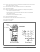
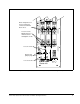
Step 5. Turn the overload relay potentiometer to the blower motor’s rated full load current. Set the overload
relay to A (Auto). See figure 1 or figure 5.
Step 6. Connect the blower motor leads to the blower motor starter’s T1, T2, and T3 terminals.
Step 7. Turn on power to the drive.
Step 8. Check for proper blower motor rotation. If the blower motor is rotating in the wrong direction;
a. Turn off, lockout, and tag power to the drive.
b. Swap the blower motor leads connected to the blower motor starter’s T1 and T2 terminals.
c. Turn on power to the drive.
d. Repeat the check for proper blower motor rotation.
Step 9. Turn off and lockout power to the drive.
Step 10. Install the cover on the drive or drive's line fuse panel, if necessary.
Step 11. Turn on power to the drive.
Kit installation is now complete.
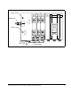
Figure 1 – Typical Blower Motor Starter (1.5 HP to 300 HP Drives)
13
53
1
14
2
A12
95
96
98
97
T3 T2 T1
TEST
TRIPPED
4
6
13FU 14FU 15FU
182 183181
At rear of fuse holder
Wiring Diagram
183/L3
182/L2
181/L1
P8-3 P8-4
P8-2
P8-1
OL
N
OL
N
2
4
6
OL
SUP
N
A2
A1
OL
OL
95
96
9897
N AUX
14
13
T1
1
15FU
14FU
3
T2
N
T3
5
13FU
P8 Connector
Set to "A"
(AUTO)
Set to rated blower
motor amps (FLA)