
User guide


Programming the Drive
4-7
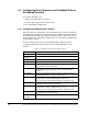
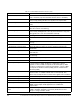
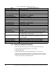
Table 4.6 – FlexPak 3000 Scheduled Drive Feedback Data
Name Description (Drive to PLC)
Word 0 Drive Status Word 1 Indicates drive status
Bit 00 Ready 0 = Not ready, 1 = Ready
Bit 01 Running 0 = Stopped, 1 = Running
Bit 02 Fault 0 = No Fault, 1 = Fault
Bit 03 Jogging 0 = Not jogging, 1 = Jogging
Bit 04 Actual direction 0 = Forward, 1 = Reverse
Bit 05 Stopping 0 = Not stopping, 1 = Stopping
Bit 06 Mode 0 = Manual, 1 = Auto
Bit 07 At speed reference 0 = Not at reference, 1 = At reference
Bit 08 Alarm 0 = No alarm, 1 = Alarm
Bit 09 Current Limit 0 = Not limited, 1 = Current limited
Bit 10 Parameter Process Error 0 = No Error, 1 = Error
Bit 11 Level Detect 1 Output 0 = Off, 1 = On
Bit 12 Level Detect 2 Output 0 = Off, 1 = On
Bit 13 Acceleration 0 = Not accelerating, 1 = Accelerating
Bit 14 Deceleration 0 = Not decelerating, 1 = Decelerating
Bit 15 Reserved Reserved
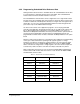
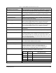
Word 1 Speed Feedback The speed of the motor as measured by the drive. Range is ±4095.
The units depend on the value of
FEEDBACK SELECT (P.200).
1 = 1/4095 of
TOP SPEED (P.011).
Word 2 Current Feedback The current being supplied by the drive. Range ±4095. Units are amps.
1 = 1/4095 of product of
MAXIMUM CURRENT (P.007) and MOTOR RATED
ARM AMPS (P.008).
Word 3 Network Output 1 Displays value selected by
NETW OUT REG 1 SELECT (P.902).
Word 4 Network Output 2 Displays value selected by
NETW OUT REG 2 SELECT (P.903).
Word 5 Network Output 3 Displays value selected by
NETW OUT REG 3 SELECT (P.904).
Word 6 Speed Feedback Gain Displays the value of
SPEED FEEDBACK GAIN, range 1000 to 32000
(1000 = 1.000).
Word 7 Speed Loop PI Initial
Value
Initial value of speed loop PI block when
CONTROL SOURCE SELECT
(P.000) is
NETWORK and Spd Loop PI Reset (bit 06, Drive Control
Word) is set to 1. Range -32768 to 32767.