
User guide


4-4
ControlNet Network Communication Option Board For Use With FlexPak 3000 and WebPak 3000 DC Drives
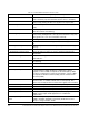
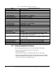
Table 4.4 – FlexPak 3000 Scheduled Drive Reference Data
Name Description (PLC to Drive)
Word 0 Drive Control Word This word consists of a set of bits written to by the PLC to control the
state of the drive (only when
CONTROL SOURCE SELECT = NETWORK).
Bit 00 Run Starts the drive in run mode. A 0-to-1 transition causes the drive to
start (if ready). Setting this bit to zero (0) does not stop the drive.
Bit 01 Stop A value of 0 stops the drive. A value of 1 allows the drive to become
ready.
Bit 02 Fault Reset Resets (only) the latched fault on a 0-to-1 transition. This bit does not
affect the contents of the fault log.
Bit 03 Jog/Stop Starts the drive in jog mode. A 0-to-1 transition causes the drive to
start (if ready). Setting this bit to zero (0) causes the drive to stop (only
after jog time-out or if no run command is asserted).
Bit 04 Forward/Reverse Operating direction command: Forward (0) or reverse (1).
Bit 05 Overwind/Underwind Selects the direction in winder applications; overwind (0) or underwind
(1).
Bit 06 Speed Loop PI Reset Selects the operational state of the Speed Loop PI block; normal (0) or
reset (1).
Bit 07 OCL Enable Disables/holds in reset (0) or enables (1) the Outer Control Loop.
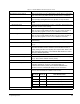
Bit 08 Fault Log Clear, Reset Clears the fault log contents on a 0-to-1 transition and resets the
latched fault.
Bit 09 Alarm Log Clear, Reset Clears the alarm log contents on a 0-to-1 transition and resets the
alarm indicator.
Bit 10 Alarm Reset Resets (only) the alarm on a 0-to-1 transition. This bit does not affect
the alarm log.
Bit 11 Memory Save Performs a memory save operation in the drive on a 0-to-1 transition.
Bit 12 - 15 Reserved Reserved
Word 1 Speed/Torque Reference This word is written to by the ControlNet network to command a speed
or torque reference. When the drive is configured as a speed
regulator, a value of 4095 corresponds to
TOP SPEED (P.011). When
the drive is configured as a torque/current regulator, a value of 4095
corresponds to
MAXIMUM CURRENT (P.007) percent of MOTOR RATED
ARM AMPS (P.008).
Word 2 Field Reference This word is written to by the ControlNet network to command a field
reference value. 1= 1/4095 of
MOTOR HOT FLD AMPS (P.510). This
value is only used by the drive if a field current regulator kit is installed.
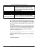
Word 3 Network Input 1 A value that is input in various places of the speed loop.
Word 4 Network Input 2 A value that is input in various places of the speed loop.
Word 5 Network Input 3 A value that is input in various places of the speed loop.
Word 6 Speed Feedback Gain Value (1000 = 1.000) multiplied by speed feedback (range 1000 to
32000. Used in simple winder applications for roll diameter
compensation.
Word 7 Speed Loop PI Initial
Value
Initial value of speed loop PI block when
CONTROL SOURCE SELECT
(P.000) =
NETWORK and Spd Loop PI Reset (bit 06, Drive Control
Word) = 1. Range -32768 to 32767.