ControlNet™ Network Communication Option Board For Use With FlexPak™ 3000 and WebPak™ 3000 DC Drives M/N 915FK2101 Instruction Manual D2-3425-3
The information in this manual is subject to change without notice. Throughout this manual, the following notes are used to alert you to safety considerations: ! ATTENTION: Identifies information about practices or circumstances that can lead to personal injury or death, property damage, or economic loss. Important: Identifies information that is critical for successful application and understanding of the product.
CONTENTS Contents Chapter 1 Introduction 1.1 Network Option Board Description .................................................................. 1-1 1.2 Where To Find Additional Information ............................................................. 1-3 1.3 Getting Assistance from Reliance Electric....................................................... 1-3 Chapter 2 Installation 2.1 Installing the Network Option Board ................................................................ 2-1 2.
6.4 6.5 6.6 II Scheduled Messaging (I/O)..............................................................................6-5 Unscheduled Messaging..................................................................................6-6 SLC500 Support...............................................................................................
List of Figures Figure 1.1 – ControlNet Network Communication Option Board .............................. 1-2 Figure 2.1 – Opening the Carrier .............................................................................. 2-1 Figure 2.2 – Removing the Carrier Shield ................................................................ 2-2 Figure 2.3 – Removing the Shield Ground Wire ....................................................... 2-2 Figure 2.4 – Installing the Network Communication Option Board ........
IV ControlNet Network Communication Option Board For Use With FlexPak 3000 and WebPak 3000 DC Drives
List of Tables Table 4.1 – Network Update Time Components...................................................... 4-1 Table 4.2 – ControlNet Scheduled Traffic Configuration Fields................................ 4-2 Table 4.3 – Data Sent/Received 8 Words (Maximum) ............................................. 4-3 Table 4.4 – FlexPak 3000 Scheduled Drive Reference Data ................................... 4-4 Table 4.5 – WebPak 3000 Scheduled Drive Reference Data................................... 4-5 Table 4.
VI ControlNet Network Communication Option Board For Use With FlexPak 3000 and WebPak 3000 DC Drives
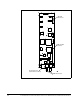
CHAPTER 1 Introduction This manual describes the ControlNet™ Network Communication Option board. (M/N 915FK2101). This kit allows a FlexPak™ 3000 or a WebPak™ 3000 DC drive to send and receive data via a control processor over the ControlNet network. WebPak 3000 drives (version 1.1 or later) require version 2.2 or later of the ControlNet Network Option board. FlexPak 3000 drives (version 4.2 or later) are compatible with all versions of the network option board.
RS-232 Connector Ribbon Cable Connector RJ-45 Connector (Network Access Port) BNC Connectors Figure 1.
1.2 Where To Find Additional Information You must be familiar with all the instruction manuals that describe your system. This can include, but is not limited to: • FlexPak 3000 DC Drive Hardware Reference, D2-3404 • FlexPak 3000 DC Drive Software Reference, D2-3405 • WebPak 3000 DC Drive Hardware Reference, D2-3443 • WebPak 3000 DC Drive Software Reference, D2-3444 • ControlNet Network System Overview, 1786-2.9 • ControlNet Cable System Component List, AG-2.
1-4 ControlNet Network Communication Option Board For Use With FlexPak 3000 and WebPak 3000 DC Drives
CHAPTER 2 Installation This section describes how to install the network option board in the drive and connect the drive to a ControlNet network. 2.1 Installing the Network Option Board ! ATTENTION: Only qualified electrical personnel familiar with the construction and operation of this equipment and the hazards involved should install, adjust, operate, or service this equipment. Read and understand this manual and other applicable manuals in their entirety before proceeding.
Step 4. Remove the screws that attach the carrier shield to the carrier. See figure 2.2. Carrier Shield Figure 2.2 – Removing the Carrier Shield Step 5. Remove the connector that attaches the shield ground wire to the drive power supply. Set the shield aside. See figure 2.3. Ground Wire Power Supply Figure 2.3 – Removing the Shield Ground Wire Step 6. Position the network option board over the standoffs. Refer to figure 2.4. Step 7.
Attach Network board to carrier’s molded standoffs using captive screws (qty. 3) Plug option board ribbon cable into Network board Figure 2.4 – Installing the Network Communication Option Board Step 9. Reattach the carrier shield ground wire to the drive power supply. Step 10. Reattach the carrier shield to the carrier. Step 11. Close the carrier and fasten it with the captive screw. Step 12. Reinstall the drive cover. 2.2 Connecting the Drive to a ControlNet Network See figure 2.
Programmable Logic Controller (PLC) Repeater Drop Cable FlexPak 3000 or WebPak 3000 Drive Note: This diagram shows redundant media being used. Tap Terminator Trunk Cable Figure 2.5 – Connecting a FlexPak 3000 Drive or a WebPak 3000 Drive to the ControlNet Network You can run a second trunk cable between your ControlNet nodes for redundant media. With redundant media, nodes send signals on two separate segments.
CHAPTER 3 Drive Configuration This chapter describes how to configure a drive for use with a ControlNet network. The sections that follow describe all of the FlexPak 3000 and WebPak 3000 drive parameters related to ControlNet operation. 3.1 Setting NETW DROP NUMBER (P.900) Use NETW DROP NUMBER (P.900) to assign a node number to the drive. The node number can be changed (through a local operator interface) only when the drive is stopped. This parameter cannot be written over the ControlNet network.
3.3 Setting CNI PROG/RUN MODE (P.915) ! ATTENTION: CNI PROG/RUN MODE (P.915) allows you to configure the drive to continue to run when the PLC is put into program mode. You must provide some form of hardwired stop in case of communication loss, since stopping the drive through the network might not be possible. Failure to observe this precaution could result in bodily injury or damage to, or destruction of, equipment. CNI PROG/RUN MODE (P.
For FlexPak 3000 drives, NETW COMM LOSS SELECT (P.901) defines how the drive will respond to network communication loss when CONTROL SOURCE SELECT (P.000) is set to NETWORK. Alarms do not cause the drive to stop. Therefore, some form of hardwired stop must be available in case of communication loss, since stopping the drive through the network might not be possible. When NETW COMM LOSS SELECT = FAULT (1), a fault is generated when network communication is lost, causing the drive to coast/DB stop.
3.6 Setting NETW OUT REG 2 SELECT (P.903) 2 SELECT (P.903) defines a parameter number whose value will be monitored and saved in the network option board’s dual-port memory. For example, setting this parameter equal to 588 will cause the value of FIELD DELTA (P.588) to be written to file address N10:48 in the dual-port memory for FlexPak 3000 drives, address N10:88 for WebPak 3000 drives. NETW OUT REG Range: -32768 to 32767 Type: Non-volatile, Tunable Default: 0 3.7 Setting NETW OUT REG 3 SELECT (P.
3.10 NETWORK KIT (P.796) NETWORK KIT (P.796) indicates whether the network option board is operating correctly in the drive. Range: PRESENT (1), NOT PRESENT (2), FAILED DIAGS (3) Type: Read-only (output) 3.11 NETW IN REG 1 (P.905) NETW IN REG 1 (P.905) indicates the value being written by the network master into file address N11:10 in the network option board’s dual-port memory. Range: -4095 to 4095 Type: Read-only (output) 3.12 NETW IN REG 2 (P.906) NETW IN REG 2 (P.
3-6 ControNet Network Communication Option Board For Use With FlexPak 3000 and WebPak 3000 DC Drives
CHAPTER 4 Programming the Drive This section describes how to program the drive over the ControlNet network. 4.1 About ControlNet Network Communication The ControlNet network transports time-critical control information (for example, drive reference and feedback information) as scheduled data, as well as non-time-critical information (for example, accessing drive parameters) as unscheduled data. The transportation of the non-time-critical information does not interfere with the time critical messages.
4.2 Configuring Drive Reference and Feedback Data as Scheduled Transfers This section describes how to: • configure scheduled traffic for the drive • control the drive using the drive reference data • use scheduled drive feedback data 4.2.1 Configuring Scheduled Data Transfers Before the drive can communicate on the ControlNet network, you must configure its scheduled traffic information by using some type of ControlNet configuration software.
4.2.2 Programming Scheduled Drive Reference Data Setting CONTROL SOURCE SELECT to NETWORK allows the scheduled data from the PLC to control the drive. If CONTROL SOURCE SELECT ≠ NETWORK, then scheduled drive reference data from the ControlNet network is not used. The scheduled drive reference data can be configured as one to eight words of data. The first word of the scheduled drive reference data is always the drive control word; it is written in element 0 of the Output file.
Table 4.4 – FlexPak 3000 Scheduled Drive Reference Data Name Description (PLC to Drive) Word 0 Drive Control Word This word consists of a set of bits written to by the PLC to control the state of the drive (only when CONTROL SOURCE SELECT = NETWORK). Bit 00 Run Starts the drive in run mode. A 0-to-1 transition causes the drive to start (if ready). Setting this bit to zero (0) does not stop the drive. Bit 01 Stop A value of 0 stops the drive. A value of 1 allows the drive to become ready.
Table 4.5 – WebPak 3000 Scheduled Drive Reference Data Name Word 0 Drive Control Word Description (PLC to Drive) This word consists of a set of bits written to by the PLC to control the state of the drive (only when CONTROL SOURCE SELECT = NETWORK). Bit 00 Section Run Starts the drive in run mode. A 0-to-1 transition causes the drive to start (if ready). Setting this bit to zero (0) does not stop the drive. Bit 01 Section Off A value of 0 stops the drive. A value of 1 allows the drive to become ready.
Table 4.5 – WebPak 3000 Scheduled Drive Reference Data (Continued) Name Description (PLC to Drive) Word 1 Speed/Torque Reference This word is written to by the ControlNet network to command a speed or torque reference. When the drive is configured as a speed regulator, a value of 4095 corresponds to TOP LINE SPEED (P.020). When the drive is configured as a torque/current regulator, a value of 4095 corresponds to MAXIMUM CURRENT (P.007) percent of MOTOR RATED ARM AMPS (P.008).
Table 4.
Table 4.
4.3.1 About MSG Instruction Timing When a Typed Read message is sent to the drive, the response is returned in under 20 ms. When a Typed Write message is sent to the drive, the message is first processed by the drive. Therefore, up to 600 ms may elapse before the response is returned. These times are applicable only when the network update time and unscheduled traffic bandwidth are not limiting factors. 4.3.
All the parameters may accessed with one message block. Any contiguous subset of the parameters may be changed without sending a new copy of the entire block. Some of the parameters are marked Config (configuration), meaning that they may only be changed while the drive is stopped. Any attempt to change the value of these parameters while the drive is in a “running” state will result in an error, and the value in the drive will not be changed.
When this occurs, the MSG instruction’s ER coil is set and an error code (=11 or 0B hex) is written into an element in N20 that corresponds to the parameter that was not accepted. For every element in N10:x there is a corresponding element in N20:x. In response to the error coil, the PLC can read N20:x to find out which parameters were not accepted. When parameters are written to, only the corresponding status words are updated.
4-12 ControlNet Network Communication Option Board For Use With FlexPak 3000 and WebPak 3000 DC Drives
CHAPTER 5 Configuring ControlLogix Applications Chapter 5 provides information and examples that explain how to use I/O Messaging to control, configure, and monitor scheduled and unscheduled data on a FlexPak 3000 or Webpak 3000 drive using a ControlNet scanner module. ! ATTENTION: The examples in this publication are intended solely for purpose of example. There are many variables and requirements with any application.
Step 1. Right-click on the I/O Configuration folder and select New Module (figure 5.2). Figure 5.2 – RSLogix 5000: New Module Selection Step 2. Select the ControlNet module used by the controller. In this example (figure 5.3), a 1756-CNB Series B ControlNet Bridge is selected.Click OK. Figure 5.
Step 3. Enter a Name, Slot number, and Revision number (figure 5.4). Click Next>. Figure 5.4 – Module Properties: Name Selection Step 4. This step is used to define controller-to-module behavior (figure 5.5). Inhibit Module inhibits/un-inhibits the connection to the module. The Major Fault check-box selects if a failure on the connection of this module causes a major fault on the controller if the connection for the module fails. Click Next>. Figure 5.
Step 5. This window (figure 5.6) is displayed for informational purposes only. Click Next>. Figure 5.6 – Module Properties: Identification/Status Screen Step 6. This window (figure 5.7) is displayed for informational purposes only. Click Finish>>. Figure 5.
Step 7. The 1756-CNB/B now appears in the I/O Configuration folder (figure 5.8). Figure 5.8 – RSLogix 5000: I/O Configuration Folder Step 8. Right-click on the 1756-CNB and select New Module (figure 5.9). Figure 5.
Step 9. To configure a FlexPak3000 drive, select the FlexPak3000 (figure 5.10). Click OK. Figure 5.10 – Select Drive Type: FlexPak 3000 Step 10. Enter a Name, Node number, and Revision number (figure 5.11). Click Next>. Important: Electronic Keying should be set to disabled. Figure 5.11 – Module Properties: Name Selection Step 11. The Requested Packet Interval (RPI) schedules the connection to move data to or from the module at least this often or the connection will fail with the RPI Not Valid error.
Important: The RPI time must be set greater than or equal to the Network Update Time (NUT). Figure 5.12 – Module Properties: RPI Selections Step 12. This window (figure 5.13) is for informational purposes only. Click Finish>>. Module Properties – Cnet Bridge: 0 (Flexpak 3000 2.1) Figure 5.
Step 13. The configured node (“FlexPak 3000” in this example) now appears under the 1756-CNB module in the I/O Configuration folder. Figure 5.14 – RSLogix: Configure Additional Nodes Screen Step 14. Repeat the previous steps for each additional node you need to configure. Step 15. In the Data Types folder, click on the Module-Defined sub-folder. When you create a module, module-defined data types and tags are automatically created.
Step 16. Select Communications / Download to download the configuration to the controller (figure 5.16). RSLogix automatically enters on-line mode when complete. Cnet_bridge:0 (FlexPak 3000 2.1) Figure 5.16 – Download to the Controller Dialog Box Step 17. An Attention symbol is located next to the Node 2 (FP3000) icon in figure 5.17, which indicates the ControlNet scanner needs to be configured. Figure 5.17 – RSLogix: Attention Symbol Step 18. Start RSNetWorx and perform the following: a.
Figure 5.18 – RSNetWorx for ControlNet Screen Step 19. The Attention symbol on the RSLogix 5000 connection tree will disappear if the network has been configured properly. You are now ready to develop your ladder logic program.
CHAPTER 6 Configuring SLC500 Applications Chapter 6 describes how to configure a SLC500 PLC on a ControlNet network with a FlexPak3000 or Webpak3000 drive. Both the 1747-SCNR and 1747-KFC15 modules are required to communicate fully with a drive and both must be configured as drops on the ControlNet network.
6.2 Network Configuration Configure the ControlNet network using RSLinx and RSNetWorx for ControlNet software. Using the parameters suggested in chapter 4 of this manual, configure scheduled traffic with RSNetWorx, by doing a scanlist configuration of the 1747-SCNR module to the drive. It is recommended that Input and Output files are used instead of M1 and M0 files, as discrete I/O is more appropriate for critical data transfer.
6.3 1747-KFC15 Set Up Unlike PLC5 or ControlLogix controllers, the unscheduled messages between the SLC controller and the drive must pass through the KFC15 module and the serial cable, included with the KFC15 module, that physically connects the module and the processor. Important: ControlNet unscheduled messaging is not fully deterministic and may be further limited by the baud rate selected for Channel 0 (RS232/DF1) communications.
In the project tree, choose Controller Properties and Controller Communications. Set the appropriate Driver, Node and Path for Communications. The Node and Path must be the ControlNet Mode of the 1747-KFC15 module. After applying all settings, download to the processor. Figure 6.3 – Controller Properties: Controller Communications Figure 6.
6.4 Scheduled Messaging (I/O) To use scheduled messaging, the Ladder Logic must include a line that sets a bit in the SCNR module. The processor must be in run or remote run. Include a line that has a coil that sets word 0, bit 10 in the SCNR module. [O:x:0/10], where x = the slot number where the SCNR module resides. Output word “0” is the SCNR command word. Input word “0” is the SCNR status word. In the example below: • O:3.3 had been set up as the output address and I:3.
Figure 6.6 – Scheduled Messaging Example 1b 6.5 Unscheduled Messaging Unscheduled communications must use PLC5 Typed Read and Write messages. In the example below, drive (Cnet mode 6) parameters at file address N10:0 through N10:9 are read into the controller registers N10:0 through N10:9. Important: For each message, the element size may not exceed the processor limit of 103 elements. Figure 6.
Figure 6.8 – Unscheduled Messaging Example 6.6 SLC500 Support For drives technical assistance, call 1-800-726-8112. For assistance from Rockwell Software, call 1-440-646-7800. To reach the Control and Information Group (SLC Modules), call 1-440-646-6800. Section 1.3 of this manual outlines the information that you need before calling for support.
6-8 ControlNet Network Communication Option Board For Use With FlexPak 3000 and WebPak 3000 DC Drives
CHAPTER 7 Register Map for FlexPak 3000 Drives Table 7.1 – File N10:x (Drive Read/Write Parameters) for FlexPak 3000 Drives File Address Parameter Name N10:0 Reserved N10:1 Parameter Number Type --- Tunable Reserved ACCELERATION TIME P.001 Tunable 1 = 0.1 s N10:2 DECELERATION TIME P.002 Tunable 1 = 0.1 s Scale N10:3 MINIMUM SPEED P.003 Tunable 1 = 1 RPM N10:4 MAXIMUM SPEED P.004 Tunable 1 = 1 RPM N10:5 POSITIVE CURRENT LIM P.005 Tunable 1 = 1% of MOTOR RATED ARM AMPS (P.
Table 7.1 – File N10:x (Drive Read/Write Parameters) for FlexPak 3000 Drives (Continued) File Address Parameter Name Parameter Number Type N10:27 OCL PI PROP GAIN P.808 Tunable 1 = 0.01 N10:28 OCL PI LEAD FREQ P.809 Tunable 1 = 0.01 rad/s Scale N10:29 OCL PI POSITIVE LIMIT P.810 Tunable 1 = 1% of TOP SPEED (P.011) N10:30 OCL PI NEGATIVE LIMIT P.811 Tunable 1 = 1% of TOP SPEED ( P.011) N10:31 OCL TRIM RANGE P.812 Tunable 1 = 1% of TOP SPEED (P.011) N10:32 OCL REFERENCE SELECT P.
Table 7.1 – File N10:x (Drive Read/Write Parameters) for FlexPak 3000 Drives (Continued) File Address Parameter Name Parameter Number Type Scale N10:57 TRIM REFERENCE SELECT P.108 Tunable 0 = REGISTER 1 = ANALOG MANUAL 2 = ANALOG IN 1 3 = NETW IN REG 1 4 = NETW IN REG 2 5 = NETW IN REG 3 6 = ANALOG IN 2 N10:58 TRIM RANGE P.109 Tunable 1 = 0.1% N10:59 TRIM MODE SELECT P.110 Tunable 0 = NO TRIM 1 = INCREMENTAL 2 = PROPORTIONAL N10:60 MOP ACCEL TIME P.115 Tunable 1 = 0.
Table 7.1 – File N10:x (Drive Read/Write Parameters) for FlexPak 3000 Drives (Continued) File Address Parameter Name Parameter Number Type Scale N10:79 METER OUT 1 SELECT P.
Table 7.1 – File N10:x (Drive Read/Write Parameters) for FlexPak 3000 Drives (Continued) File Address Parameter Name N10:82 METER OUT N10:83 Parameter Number Type Scale 2 SELECT P.
Table 7.1 – File N10:x (Drive Read/Write Parameters) for FlexPak 3000 Drives (Continued) File Address N10:99 Parameter Name RESERVED Parameter Number Type --- --- Scale Reserved (future parameter expansion) | N10:149 N10:150 CONTROL SOURCE SELECT P.000 Config 0 = TERMBLK 1 = KEYPAD 2 = SERIAL 3 = NETWORK N10:151 CNI PROG/RUN MODE P.915 Config 0 = STOP 1 = USE LAST REF 2 = USE TRMBLK CNTL N10:152 MOTOR RATED ARM AMPS P.008 Config 1 = 0.1 amp N10:153 MOTOR RATED ARM VOLTS P.
Table 7.1 – File N10:x (Drive Read/Write Parameters) for FlexPak 3000 Drives (Continued) File Address Parameter Name Parameter Number Type Scale N10:166 ANLG TACH VOLTS/1000 P.203 Config 1 = 0.1 volts/1000 RPM N10:167 PULSE TACH PPR P.207 Config 1 = 1 PPR N10:168 PULSE TACH QUADRATURE P.208 Config 0 = OFF, 1 = ON N10:169 OCL PROP TRIM SELECT P.813 Config 0 = DISABLED, 1 = ENABLED N10:170 OCL FEEDBACK SELECT P.
Table 7.1 – File N10:x (Drive Read/Write Parameters) for FlexPak 3000 Drives (Continued) File Address Parameter Name Parameter Number Type Scale N10:186 DIG OUT 2 SELECT P.411 Config 0 = LEVEL DETECT 1 OUTPUT 1 = LEVEL DETECT 2 OUTPUT 2 = IN CURRENT LIMIT 3 = DRIVE READY 4 = NETW COMM STATUS 5 = NETW IN REG 1 (BIT 0) 6 = NETW IN REG 2 (BIT 0) 7 = NETW IN REG 3 (BIT 0) N10:187 DIG OUT 2 CONTACT TYP P.412 Config 0 = NORMAL OPEN 1 = NORMAL CLOSED N10:188 ANLG AUTO SIGNAL TYPE P.
Table 7.1 – File N10:x (Drive Read/Write Parameters) for FlexPak 3000 Drives (Continued) File Address Parameter Name 2 SELECT Parameter Number Type P.
Table 7.1 – File N10:x (Drive Read/Write Parameters) for FlexPak 3000 Drives (Continued) File Address Parameter Name Parameter Number Type Scale N10:195 FREQ OUT SELECT P.
Table 7.
Table 7.2 – File N11:x (Drive Display Data (Read Only)) for FlexPak 3000 Drives (Continued) File Address Parameter Name Parameter Number --- Description N11:9 Network Output Reg 3 (5 or 10 ms update) Value of parameter from NETW OUT REG 3 SELECT (P.904) N11:10 NETW IN REG 1 P.905 Present value of Network Input Register 1 N11:11 NETW IN REG 2 P.906 Present value of Network Input Register 2 N11:12 NETW IN REG 3 P.
Table 7.2 – File N11:x (Drive Display Data (Read Only)) for FlexPak 3000 Drives (Continued) File Address N11:20 Parameter Name ANALOG MANUAL Parameter Number Description P.192 Analog Manual mode reference value, after scaling Selected speed source value REFERENCE N11:21 SPD SOURCE SELECT OUT P.193 N11:22 ANALOG MAN TRIM REF P.194 Trim reference value when analog input used for trim N11:23 DRAW PERCENTAGE OUT P.196 Product of selected trim reference and TRIM RANGE (P.
Table 7.2 – File N11:x (Drive Display Data (Read Only)) for FlexPak 3000 Drives (Continued) File Address Parameter Name Parameter Number Description N11:47 DIG IN 2 P.496 Digital input 2 (terminal 60 on the I/O Expansion board) Preset B N11:48 DIG IN 3 P.497 Digital input 3 (terminal 62 on the I/O Expansion board) MOP decrease N11:49 DIG IN 4 P.498 Digital input 4 (terminal 63 on the I/O Expansion board) MOP increase N11:50 DIG IN 5 P.
Table 7.2 – File N11:x (Drive Display Data (Read Only)) for FlexPak 3000 Drives (Continued) File Address Parameter Name N11:73 NETW COMM STATUS N11:74 NETW TYPE & VERSION Parameter Number Description P.908 0 = NOT ACTIVE, 1 = ACTIVE P.909 TV.VV: T = Network type 1, 2 = AutoMax, Profibus, InterBus 4 = DeviceNet 5 = ControlNet V.VV = Network board firmware version number P.
Table 7.
CHAPTER 8 Register Map for WebPak 3000 Drives Table 8.1 – File N10:x (Drive Read/Write Parameters) for WebPak 3000 Drives File Address Parameter Name Parameter Number Type Scale --- Tunable Reserved ACCELERATION TIME P.001 Tunable 1 = 0.1 s N10:2 DECELERATION TIME P.002 Tunable 1 = 0.1 s N10:3 MINIMUM SPEED P.003 Tunable 1 = 1 RPM N10:4 MAXIMUM SPEED P.004 Tunable 1 = 1 RPM N10:5 POSITIVE CURRENT LIM P.005 Tunable 1 = 1% of MOTOR RATED ARM AMPS (P.
Table 8.1 – File N10:x (Drive Read/Write Parameters) for WebPak 3000 Drives (Continued) File Address Parameter Name Parameter Number Type Scale N10:28 WINDER CORE DIA 2 P.824 Tunable 1 = 1.00 in N10:29 WINDER CORE DIA 3 P.825 Tunable 1 = 1.00 in N10:30 DIAMETER ACCEL RATE P.823 Tunable 1 = 0.001 in/s N10:31 DIAMETER DECEL RATE P.827 Tunable 1 = 0.001 in/s N10:32 DIAMETER REGISTER P.874 Tunable 1 = 1.000 N10:33 DIAMETER/TAPER SELECT P.
Table 8.1 – File N10:x (Drive Read/Write Parameters) for WebPak 3000 Drives (Continued) File Address Parameter Name Parameter Number Type Scale N10:67 DANCER ACCEL TIME P.873 Tunable 1 = 0.1 s N10:68 DANCER DECEL TIME P.819 Tunable 1 = 0.1 s N10:69 MAX DANCER LOAD P.831 Tunable N10:70 MIN DANCER LOAD P.832 Tunable N10:71 FRICTION LOSS P.123 Tunable 1 = 0.1% N10:72 WINDAGE LOSS P.243 Tunable 1 = 0.1% N10:73 WIDTH/BUILDUP FACTOR P.872 Tunable 1 = 0.
Table 8.1 – File N10:x (Drive Read/Write Parameters) for WebPak 3000 Drives (Continued) File Address Parameter Name Parameter Number Type Scale N10:99 ANALOG TACH ZERO ADJ P.202 Tunable N10:100 ARM VOLTAGE GAIN ADJ P.204 Tunable 1 = 0.001 N10:101 ARM VOLTAGE ZERO ADJ P.205 Tunable N10:102 LINE SPEED GAIN ADJ P.101 Tunable 1 = 0.001 N10:103 LINE SPEED ZERO ADJ P.102 Tunable N10:104 DIAMETER/TAPER GAIN P.104 Tunable 1 = 0.001 N10:105 DIAMETER/TAPER ZERO P.
Table 8.1 – File N10:x (Drive Read/Write Parameters) for WebPak 3000 Drives (Continued) File Address Parameter Name Parameter Number Type Scale N10:114 ANLG OUT 2 GAIN ADJ P.401 Tunable 1 = 0.001 N10:115 ANLG OUT 2 ZERO ADJ P.403 Tunable N10:116 ANLG OUT 2 SELECT P.
Table 8.1 – File N10:x (Drive Read/Write Parameters) for WebPak 3000 Drives (Continued) File Address Parameter Name Parameter Number Type Scale N10:129 SELF TUNE BRIDGE P.220 Tunable 0 = FORWARD, 1 = REVERSE N10:130 OPEN SCR SENSITIVITY P.600 Tunable 1 = 1% N10:131 OPEN SCR TRIP THRESH P.601 Tunable N10:132 Clock Functions N10:133 | N10:149 Reserved N10:150 Read = Elapsed time (hours) since last power up. Write bit 0 = 1 Reset clock to zero; any other value written has no effect.
Table 8.1 – File N10:x (Drive Read/Write Parameters) for WebPak 3000 Drives (Continued) File Address Parameter Name Parameter Number Type Scale N10:167 NEG CURRENT LIM SEL P.224 Config 0 = REGISTER 1 = PARALLEL OCL 2 = NETW IN REG 1 3 = NETW IN REG 2 4 = NETW IN REG 3 N10:168 NEG CUR LIM INV EN P.226 Config 0 = DISABLED, 1 = ENABLED N10:169 INV FAULT AVOID SEL P.312 Config 0 = DISABLED 1 = FAULT IMMEDIATELY 2 = DELAY BEFORE FAULT N10:170 FEEDBACK SELECT P.
Table 8.1 – File N10:x (Drive Read/Write Parameters) for WebPak 3000 Drives (Continued) File Address Parameter Name Parameter Number Type Scale N10:194 FIELD CURRENT 1 P.522 Config 1 = 0.01 amp N10:195 FIELD CURRENT 2 P.523 Config 1 = 0.01 amp N10:196 FIELD CURRENT 3 P.524 Config 1 = 0.01 amp N10:197 FIELD CURRENT 4 P.525 Config 1 = 0.01 amp N10:198 FIELD CURRENT 5 P.526 Config 1 = 0.01 amp N10:199 FIELD CURRENT 6 P.527 Config 1 = 0.
Table 8.1 – File N10:x (Drive Read/Write Parameters) for WebPak 3000 Drives (Continued) File Address Parameter Name Parameter Number Type Scale N10:218 DIG OUT 1 CONTACT TYP P.410 Config 0 = NORMAL OPEN 1 = NORMAL CLOSED N10:219 DIG OUT 2 SELECT P.
Table 8.1 – File N10:x (Drive Read/Write Parameters) for WebPak 3000 Drives (Continued) File Address N10:224 8-10 Parameter Name ANLG OUT 3 SELECT Parameter Number Type P.
Table 8.1 – File N10:x (Drive Read/Write Parameters) for WebPak 3000 Drives (Continued) File Address Parameter Name 4 SELECT Parameter Number Type P.
Table 8.1 – File N10:x (Drive Read/Write Parameters) for WebPak 3000 Drives (Continued) File Address Parameter Name Parameter Number Type Scale N10:228 FREQ OUT SELECT P.
Table 8.1 – File N10:x (Drive Read/Write Parameters) for WebPak 3000 Drives (Continued) File Address N10:231 Parameter Name LEVEL DETECT 1A SEL Register Map for WebPak 3000 Drives Parameter Number Type P.
Table 8.1 – File N10:x (Drive Read/Write Parameters) for WebPak 3000 Drives (Continued) File Address N10:232 8-14 Parameter Name LEVEL DETECT 1B SEL Parameter Number Type P.
Table 8.1 – File N10:x (Drive Read/Write Parameters) for WebPak 3000 Drives (Continued) File Address N10:233 Parameter Name LEVEL DETECT 2A SEL Register Map for WebPak 3000 Drives Parameter Number Type P.
Table 8.1 – File N10:x (Drive Read/Write Parameters) for WebPak 3000 Drives (Continued) File Address Parameter Name Type P.
Table 8.
Table 8.2 – File N11:x (Drive Display Data (Read Only)) for WebPak 3000 Drives (Continued) File Address Parameter Name Parameter Number --- Description N11:9 Network Output Reg 3 Value of parameter from NETW OUT REG 3 SELECT (P.904) N11:10 NETW IN REG 1 P.905 Present value of Network Input Register 1 N11:11 NETW IN REG 2 P.906 Present value of Network Input Register 2 N11:12 NETW IN REG 3 P.
Table 8.2 – File N11:x (Drive Display Data (Read Only)) for WebPak 3000 Drives (Continued) File Address Parameter Name Parameter Number Description N11:20 SPEED CROSS OVER P.133 Speed loop cross over frequency N11:21 SPEED PI WLD OUT P.250 Value of the speed loop PI low frequency N11:22 SPEED PI KP OUT P.251 Value of the speed loop PI proprotional gain N11:23 SPEED LAG FREQ OUT P.252 Value of the speed loop lag frequency N11:24 DRAW PERCENTAGE OUT P.
Table 8.2 – File N11:x (Drive Display Data (Read Only)) for WebPak 3000 Drives (Continued) File Address Parameter Name Parameter Number Description N11:51 TENSION SETPOINT IN P.492 Digital value of the tension setpoint input after gain and zero have been applied N11:52 TENSION/DANCER FDBK P.493 Digital value of the tension/dancer feedback input after gain and zero have been applied N11:53 DANCER LOADING P.820 Rate-limited and scaled value of TENSION DEMAND (P.
Table 8.2 – File N11:x (Drive Display Data (Read Only)) for WebPak 3000 Drives (Continued) File Address Parameter Name Parameter Number Description N11:77 POSITION VERNIER P.241 Output of the position major loop N11:78 POS LL WLO OUT P.246 Value of the position loop lead/lag low frequency N11:79 POS LL RATIO OUT P.247 Value of the position loop lead/lag ratio N11:80 POS PI KP OUT P.248 Value of the position loop PI proportional gain N11:81 POS PI WLD OUT P.
Table 8.
Table 8.
8-24 ControlNet Network Communication Option Board For Use With FlexPak 3000 and WebPak 3000 DC Drives
CHAPTER 9 Communication Error Codes Table 9.1 defines the error codes that are returned by the drive for Typed Read and Typed Write messages. Table 9.
9-2 ControlNet Network Communication Option Board For Use With FlexPak 3000 and WebPak 3000 DC Drives
GLOSSARY configuration manager node - The node responsible for distributing ControlNet configuration data to all nodes on the network. configurable (parameter) - A parameter that can be adjusted or changed only when the drive is stopped. ControlNet network - A communication architecture that allows the exchange of messages between Rockwell Automation products and certified third-party products. connection - An opened communication path between two nodes on a ControlNet network.
NUT (Network Update Time) - Repetitive time interval in which data can be sent on the ControlNet network. redundant media - A dual cable system that lets you receive the best signal over a network. repeater - A two-port active physical-layer device that reconstructs and retransmits all traffic it hears on one segment to another segment. sheduled transfer - Deterministic and repeatable transfers that are continuous and asynchronous to the ladder-logic program scan.
INDEX B E BNC connectors, 1-1, 1-2 board installation, 2-1 error codes, 9-1 C F (P.915), 3-2 communication error codes, 9-1 communication loss response FlexPak 3000 drives, 3-3 WebPak 3000 drives, 3-2 connecting drive to ControlNet network, 2-3 to 2-4 connectors 9-pin D-shell, 1-1 BNC, 1-1 locations of, 1-2 ribbon cable, 1-1 RJ-45, 1-1 contacting Reliance Electric, 1-3 CONTROL SOURCE SELECT (P.
WebPak 3000 drives, 8-17 to 8-22 N12:x (drive reference and feedback data) FlexPak 3000 drives, 7-16 WebPak 3000 drives, 8-23 NETW COMM LOSS SELECT (P.901), 3-2 to 3-3 NETW COMM STATUS (P.908), 3-4 NETW DROP NUMBER (P.900), 3-1 NETW IN REG 1 (P.905), 3-5 NETW IN REG 2 (P.906), 3-5 NETW IN REG 3 (P.907), 3-5 NETW OUT REG 1 SELECT (P.902), 3-3 NETW OUT REG 2 SELECT (P.903), 3-4 NETW OUT REG 3 SELECT (P.904), 3-4 NETW TYPE & VERSION (P.
U.S. Drives Technical Support Tel: (1) 262.512.8176, Fax: (1) 262.512.2222, Email: support@drives.ra.rockwell.com, Online: www.ab.com/support/abdrives Publication D2-3425-3 – February 2005 Copyright © 2005 Rockwell Automation, Inc. All Rights Reserved. Printed in USA.