
Hardware Owner's manual

Publication S-3062 – November 1997
Table of Illustrations
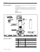
Figure P.1
Typical Dimension Sheet
. . . . . . . . . . . . . . . . . . . . . . . .
P-2
Figure 1.1
Typical 3FD86N Enclosure with Standard Options
. . . . .
1-3
Figure 2.1
Minimum Sling Angle Requirement
. . . . . . . . . . . . . . . . .
2-3
Figure 2.2
Typical Lifting (End View)
. . . . . . . . . . . . . . . . . . . . . . . .
2-4
Figure 2.3
Typical Lifting (Front Views)
. . . . . . . . . . . . . . . . . . . . . .
2-4
Figure 2.4
Joining Enclosure Sections (End Panel Outside Views)
.
2-5
Figure 2.5
FD86N Enclosure with End Plates for Connection
to a Bulletin 2100 MCC
. . . . . . . . . . . . . . . . . . . . . . . . . .
2-6
Figure 2.6
Installing a Bus Bar Assembly to an FD86N Enclosure
.
2-8
Figure 2.7
Installing a Pull Box to a Bus Bar Enclosure
. . . . . . . . . .
2-9
Figure 2.8
Installing an Equipment Enclosure to the
FD86N Enclosure
. . . . . . . . . . . . . . . . . . . . . . . . . . . . .
2-10
Figure 2.9
Installing an Air Conditioner to the Left or Right End of the
FD86N Enclosure
. . . . . . . . . . . . . . . . . . . . . . . . . . . . .
2-11
Figure 2.10
Installing a Mechanical Door Interlock Link between
FD86N Enclosures
. . . . . . . . . . . . . . . . . . . . . . . . . . . .
2-12
Figure 3.1
Splicing Single Bus Bar Assemblies
. . . . . . . . . . . . . . . .
3-1
Figure 3.2
Splicing Parallel Bus Bar Assemblies
. . . . . . . . . . . . . . .
3-2
Figure 3.3
Typical Installation of Incoming AC Bus Bar
Tabs (Staggered)
. . . . . . . . . . . . . . . . . . . . . . . . . . . . . .
3-3
Figure 3.4
Typical Installation of Incoming AC Bus Bar Tabs (Inline)
3-3
Figure 3.5
AC Bus Bar Tab Hardware Orientation
. . . . . . . . . . . . . .
3-4
Figure 3.6
Typical 4
″
Drop Tab Connections
. . . . . . . . . . . . . . . . . .
3-5
Figure 3.7
Typical 6
″
Drop Tab Connections
. . . . . . . . . . . . . . . . . .
3-6
Figure 3.8
Installing a Sheet Metal Joiner for Bus Bar Enclosures
(FD86N to FD86N)
. . . . . . . . . . . . . . . . . . . . . . . . . . . . .
3-7