FD86N Drive Systems Enclosure Hardware Installation Manual
Important User Information The illustrations shown in this guide are intended solely for purposes of example. Since there are many variables and requirements associated with any particular installation, Rockwell Automation Drive Systems does not assume responsibility or liability (to include intellectual property liability) for actual use based upon the examples shown in this publication.
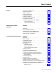
Table of Contents Preface Who Should Use this Manual . . . . . . . . . . . . . . . . . . . . . . . . . . . . . . Purpose of this Manual . . . . . . . . . . . . . . . . . . . . . . . . . . . . . . . . . . . Safety Precautions . . . . . . . . . . . . . . . . . . . . . . . . . . . . . . . . . . . . . . How to Use this Manual . . . . . . . . . . . . . . . . . . . . . . . . . . . . . . . . . . Contents of this Manual . . . . . . . . . . . . . . . . . . . . . . . . . . . . . . . . . . Related Documentation . .
toc–ii Table of Contents Joining Bus Bar Assemblies Chapter 3 Introduction . . . . . . . . . . . . . . . . . . . . . . . . . . . . . . . . . . . . . . . . . . . . 3-1 Before You Begin. . . . . . . . . . . . . . . . . . . . . . . . . . . . . . . . . . . . . . . . 3-1 Splicing Single Bus Bar Assemblies . . . . . . . . . . . . . . . . . . . . . . . . . 3-1 Splicing Parallel Bus Bar Assemblies . . . . . . . . . . . . . . . . . . . . . . . . 3-2 Installing Bus Bar Tabs for Incoming Power . . . . . . . . . . .
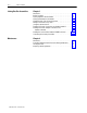
Table of Illustrations Figure P.1 Typical Dimension Sheet . . . . . . . . . . . . . . . . . . . . . . . . P-2 Figure 1.1 Typical 3FD86N Enclosure with Standard Options. . . . . 1-3 Figure 2.1 Minimum Sling Angle Requirement. . . . . . . . . . . . . . . . . 2-3 Figure 2.2 Typical Lifting (End View) . . . . . . . . . . . . . . . . . . . . . . . . 2-4 Figure 2.3 Typical Lifting (Front Views) . . . . . . . . . . . . . . . . . . . . . . 2-4 Figure 2.4 Joining Enclosure Sections (End Panel Outside Views).
toi-ii Table of Illustrations Figure 3.9 Installing a Sheet Metal Joiner on an Overhead Cable Routing Box (FD86N to SA3000 or SB3000) . . . . . . . . . . 3-7 Figure 3.10 Installing DC Bus Bar Connections from the FD86N Enclosure to an MCC. . . . . . . . . . . . . . . . . . . . . . 3-8 Figure 3.11 Installing the DC Bus Bar Adapter Connections between an SA3000 or SB3000 and a DC Bus Bar Assembly on the FD86N Enclosure . . . . . . . . . . . . . . . . . . . . . . . . . 3-9 Figure 3.
Preface Preface Please read this preface to familiarize yourself with the rest of this manual. This preface describes: • • • • • • • • who should use this manual the purpose of this manual safety precautions how to use this manual contents of this manual conventions used in this manual drive system receiving information how to contact Rockwell Automation support Who Should Use this Manual Use this manual if you are responsible for installing or handling the FD86N enclosure.
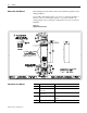
P-2 Preface How to Use this Manual This manual presents information in the order in which it is typically needed during installation. Occasionally, this manual requires you to refer to your wiring schematic or Dimension Sheet for information specific to your system. Check your wiring package for these drawings. A sample Dimension Sheet is shown in Figure P.1. Figure P.
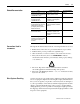
Preface Related Documentation Conventions Used in this Manual For Read This Document P-3 Document Number Additional information on joining and splicing together Bulletin 2100 CENTERLINE™ MCCs Instructions—Joining and Splicing Vertical Sections 2100-5.1 Details on receiving, handling, and storing Bulletin 2100 CENTERLINE MCCs Instructions—Receiving, Handling, and Storing Motor Control Centers 2100-5.
P-4 Preface Rockwell Automation Drive Systems Support Rockwell Automation offers support services worldwide, with Sales/ Support Offices, authorized distributors, and authorized Systems Integrators located throughout the United States, plus Rockwell Automation representatives in every major country in the world.
Chapter 1 Overview of the FD86N Enclosure Introduction This chapter provides general information about the FD86N enclosure. What is the FD86N Enclosure? The control enclosure described in this manual is a Rockwell Automation Drive Systems product. The FD86N enclosure is of deadback construction and can consist of one or more enclosures fastened together. Enclosures fastened together form a rigid, free-standing enclosure lineup assembly designed to accommodate a drive system.
1-2 Overview of the FD86N Enclosure Standard Options of the FD86N Enclosure FD86N enclosures can include: Bulletin 2100 MCC Compatibility The FD86N enclosure connects to any Bulletin 2100 motor control center that: • • • • • • • electrical door interlocks mechanical door interlocks air conditioning (end panel mounted) hood mounted equipment enclosure provisions for standard overhead AC and DC bus assemblies a safety ground bus interior lighting • is at least 20″ deep with a power bus and control bus
Overview of the FD86N Enclosure 1-3 Figure 1.
1-4 Overview of the FD86N Enclosure This page intentionally left blank.
Chapter 2 Installing the FD86N Enclosure Introduction This chapter provides procedures for unpacking and installing the FD86N enclosure. It also provides procedures for fastening enclosures together, installing conduit, and installing bus assemblies, pull boxes, equipment enclosures, and air conditioning units to the enclosure. Before You Begin Before you begin enclosure installation, be sure to have: • For skid hardware: Socket or box wrenches for 3⁄8″ hardware.
2-2 Installing the FD86N Enclosure Site Planning When preparing the installation site for the enclosure, you must provide: • Adequate space for the enclosure and associated equipment. • Adequate support for the enclosure and associated equipment. • Entry and exit provisions for the wiring. Space Requirements You must have enough clearance around the enclosure to provide unrestricted ventilation and room to service the equipment. Recommended clearance requirements are: • • • • Front: 36″ (914.
Installing the FD86N Enclosure Lifting the Enclosure 2-3 For lifting instructions, see the Dimension Sheet for your enclosure and Figures 2.1, 2.2, and 2.3. ! ATTENTION: When detaching skids, be aware that the enclosure can be top-heavy. Exercise caution. ATTENTION: When the enclosure is removed from the skids, brace and block the enclosure until it is permanently secured. When lifting the enclosure: • • • • • • • • • Use slings for pickup points. Use slings with load-rated safety hooks or shackles.
2-4 Installing the FD86N Enclosure Figure 2.2 Typical Lifting (End View) Sling Lifting Angle Typical End View Figure 2.
Installing the FD86N Enclosure Anchoring and Mounting the Enclosure 2-5 Before final anchoring of the enclosure, make sure the equipment is level and fully supported at all anchor points. Use steel shims as necessary. If it is not level and supported, the enclosure or controls can be distorted, causing wiring stresses, broken components, or improper environmental sealing. Refer to your Dimension Sheet to determine mounting requirements and mounting hole locations.
2-6 Installing the FD86N Enclosure Joining Control Enclosures to Bulletin 2100 MCCs For multi-enclosure control lineups, you might need to join enclosure sections in the field. Holes are provided in the end panels for this purpose. To join the enclosure sections, install M6 × 16 or ¼-20×½″ thread-forming screws in at least twelve holes as equally spaced around the perimeter of the enclosure as is practical.
Installing the FD86N Enclosure Protecting Ventilated Control Enclosure Equipment During Installation 2-7 During installation and maintenance, the enclosure doors will be open, which could allow airborne particles into the enclosure. Ensure that the environment is clean and free of airborne particles. If there are airborne particles, cover the enclosure to protect the electrical control equipment in the enclosure.
2-8 Installing the FD86N Enclosure Installing a Typical Bus Bar Assembly Hardware needed: • Five M6 or ¼-20 thread-forming screws per enclosure bay. To install a bus bar assembly to the FD86N enclosure: 1. Place the bus bar assembly over the cutouts on the top of the FD86N enclosure. Use the lifting points shown in Figure 2.6. Do not lift the bus bar assembly using a hook in the bus bar holes. 2. Align the mounting holes. Refer to Figure 2.6. 3.
Installing the FD86N Enclosure Installing a Pull Box to a Bus Bar Enclosure 2-9 Hardware needed: • Six M6 or ¼-20 thread-forming screws. To install a pull box to the bus bar enclosure: 1. Remove the split or top access cover from the pull box. Refer to Figure 2.7. 2. Place the pull box on the bus bar enclosure over the cutout. 3. Align the mounting holes. Refer to Figure 2.7. 4. Fasten the pull box to the bus bar enclosure using the M6 or ¼-20 threadforming screws. 5. Reinstall the access covers.
2-10 Installing the FD86N Enclosure Installing an Equipment Enclosure to the FD86N Enclosure Hardware needed: • Eight M6 or ¼-20 thread-forming screws. To install an equipment enclosure to the FD86N enclosure: 1. Remove the split or top access cover from the equipment enclosure. Refer to Figure 2.8. 2. Place the equipment enclosure on the FD86N enclosure over the appropriate cutout. 3. Align the mounting holes. Refer to Figure 2.8. 4.
Installing the FD86N Enclosure Installing an Air Conditioning Unit to the FD86N Enclosure 2-11 To install an air conditioning unit on the FD86N enclosure: 1. Cut the plug from the power cord. Strip the wires as needed. 2. Run the power cord through the feed-through hole in the end panel. 3. Mount the air conditioner using the 16 pieces of hardware supplied on the FD86N enclosure. Refer to Figure 2.9. 4. Connect the air conditioning wiring to the terminal board provided in the FD86N enclosure.
2-12 Installing the FD86N Enclosure Installing a Mechanical Door Interlock Link between FD86N Enclosures To install a mechanical door interlock link between FD86N enclosures, refer to Figure 2.10. Figure 2.
Chapter 3 Joining Bus Bar Assemblies Introduction This chapter provides the instructions for splicing bus bars, joining bus bar assemblies, and connecting ground buses and cables. Before You Begin Before you begin this procedure, be sure to have these tools: • Socket and box wrenches for ½″ hardware. • Torque wrench with ½″ socket. • Drive bit for recessed 6-lobe, Torx type screws (M6 x 16). Torque all splice connections to between 45 and 55 lb-ft (61 to 75 Nm).
3-2 Joining Bus Bar Assemblies Splicing Parallel Bus Bar Assemblies To splice parallel bus bar assemblies together: 1. Verify that this splice hardware is present. All hardware is grade 5. • ½-13 hex nuts • ½″ conical washers • ½″ flat washers • ½-13 x 2-¼ hex head cap screws ! ATTENTION: Use the hardware furnished with the bus bar splice assembly. 2. Verify that contact surfaces are free of dirt and debris. 3. See Figure 3.2 for installation. Figure 3.
Joining Bus Bar Assemblies Installing Bus Bar Tabs for Incoming Power 3-3 Incoming bus bar tabs might have been mounted upside down for shipment. Reinstall bus bar tabs in the upright position as shown in Figures 3.3 and 3.4. Important: Use the hardware furnished with the bus bar tabs. To install bus bar tabs for incoming power connections: 1. Verify that contact surfaces are free of dirt and debris. 2. See Figure 3.5 for installation and for correct bolt orientation. Figure 3.
3-4 Joining Bus Bar Assemblies Figure 3.
Joining Bus Bar Assemblies Making Connections to Drop Tabs 3-5 To make connections to drop tabs: 1. Verify that contact surfaces are free of dirt and debris. 2. For 4″ drop tabs, see Figure 3.6 for installation and correct bolt orientation. For 6″ drop tabs, see Figure 3.7 for installation and correct bolt orientation. Figure 3.
3-6 Joining Bus Bar Assemblies Figure 3.
Joining Bus Bar Assemblies Joining Bus Bar Enclosures 3-7 Hardware needed: M6 or ¼-20 thread-forming screws. To join bus bar enclosures from an FD86N enclosure to FD86N enclosure, see Figure 3.8. To join bus bar enclosures from an FD86N enclosure to an SA3000 or SB3000, see Figure 3.9. Figure 3.8 Installing a Sheet Metal Joiner for Bus Bar Enclosures (FD86N to FD86N) M6 or ¼-20 Thread-Forming Screw Bus Bar Enclosure Sheet Metal Joiner Bus Bar Enclosure Figure 3.
3-8 Joining Bus Bar Assemblies Installing DC Bus Bar Connections to a Bulletin 2100 MCC To join DC bus bars to an MCC: 1. Remove the supplied hardware from the bus tab. 2. Make the bus connection between the FD86N enclosure and MCC. 3. Reinstall the hardware, oriented as shown in Figure 3.10. Figure 3.
Joining Bus Bar Assemblies Installing DC Bus Bar Adapter Connections to an SA3000 or SB3000 3-9 To join DC bus bar adapters to an SA3000 or SB3000: 1. Remove the supplied hardware from the bus bar. Refer to Figure 3.11. 2. Make the bus bar adapter connection between SA3000 and SB3000 and the FD86N enclosure. 3. Reinstall the hardware, oriented as shown in Figure 3.11. Important: Figure 3.11 shows connections to a parallel bus bar.
3-10 Joining Bus Bar Assemblies Installing the Ground Cables between FD86N Enclosures To install the ground cables between FD86N enclosures, see Figure 3.12 for ground cable location and hardware orientation. The control enclosure ground bus can be mounted at the top or the bottom of the control panel. Figure 3.
Joining Bus Bar Assemblies Connecting the Incoming Ground Bus 3-11 To connect the incoming ground bus, see figures 3.13 and 3.14. Note: Use the jumper and hardware furnished with the bus bar assembly. Figure 3.
3-12 Joining Bus Bar Assemblies Figure 3.
Chapter 4 Maintenance Introduction Maintenance of the FD86N enclosure consists of protecting the enclosures during installation and cleaning the filter periodically. Protecting Ventilated Control Enclosures During Maintenance During maintenance, the enclosure doors will be open, which could allow airborne particles into the enclosure. Ensure that the environment is clean and free of airborne particles. If there are airborne particles, cover the enclosure to protect the electrical control equipment.
4-2 Maintenance This page intentionally left blank.
Index A G air conditioning unit installing, 2-11 anchoring enclosure, 2-5 ground bus, 3-11 cables, 3-10 B H bus bar enclosure installing a pull box, 2-9 installing adapter connections to SA3000, 3-9 SB3000, 3-9 assembly, 2-8 joining assemblies, 3-1 enclosures, 3-7 splicing parallel assemblies, 3-2 single assemblies, 3-1 tabs installing for incoming power, 3-3 handling, 2-1 C conduit, installing, 2-7 control enclosures joining sections, 2-5 joining to MCCs, 2-6 D dimension sheet sample, P-2 drop ta
I-2 Index T V Type 12 enclosures, 2-5, 2-6, 2-7 ventilated enclosures protecting, 2-7, 4-1 U unpacking, 2-1 W wiring entry and exit provisions, 2-2 Publication S-3062 – November 1997
Rockwell Automation helps its customers receive a superior return on their investment by bringing together leading brands in industrial automation, creating a broad spectrum of easy-to-integrate products. These are supported by local technical resources available worldwide, a global network of system solutions providers, and the advanced technology resources of Rockwell. Worldwide representation.