
Energy Saving Package Instruction Manual


B-16 FanMaster Diagrams
Allen-Bradley® FanMaster™ Energy Saving Package Installation Manual - Publication FANM-IN001B-EN-P – December, 2009 PN-65329
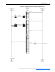
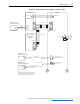
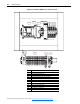
Figure B.15 FanMaster, NEMA/UL Type 1 Enclosure Layout
SLOT 1
PLC
SLOT 0
ESC OK
PS1CB2
CR1
CR2
CR3
CR4
TB3
TB2
CB1 TB1
Label Component
Slot 0 MicroLogix 1100 Programmable Controller
Slot 1 Analog Input Expansion Module
CB2 Circuit Breaker for controller and analog input module power
PS1 Power Supply 120V AC input / 24V DC output
CR1 Contact Relay for supply “fan running” signal
CR2 Auxiliary Contact Relay for supply “fan running” signal
CR3 Spare Contact Relay for customer use
CR4 Contact Relay for BAS Controller “start” signal
TB3 Modbus communication adapter
TB2 Primary I/O terminal block
CB1 Circuit Breaker for panel power
TB1 Power input terminal block