
Energy Saving Package Instruction Manual

2-2 FanMaster Installation
Allen-Bradley® FanMaster™ Energy Saving Package Installation Manual - Publication FANM-IN001B-EN-P – December, 2009 PN-65329
Installation Considerations
Consider and plan for the following when installing FanMaster for
integration with an AHU:
• The existing BAS control supply fan start/stop signal. Two relays are
provided for interfacing to the BAS fan start/stop signal. The relay
installed in the FanMaster enclosure accommodates a 120V AC signal.
A second relay is shipped loose and accommodates a 24V AC signal. If
a signal other than 24V or 120V AC is used, you must purchase and
install the appropriate relay separately. The Allen-Bradley 700-HK
family of relays provides coil voltages from 6V AC…240V AC or 6V
DC…48V DC. More information is provided on the Allen-Bradley web
site at: http://www.ab.com/en/epub/catalogs/12768/229240/229266/
229643/229701/tab3.html
• The existing BAS outside air damper position control signal (used with
constant ventilation option only). FanMaster provides I/O connections
for a 4…20 mA signal only. If the BAS control signal is 0…10V DC or
0…135 Ohms, a converter adapter must be purchased separately for
both the input and output signals.
• When installing FanMaster with a Variable Frequency Drive, the
following firmware revisions must be used:
– PowerFlex 400, v1.004 and later
– PowerFlex 70EC v3.001 and later
– PowerFlex 700VC v4.001 and later
– PowerFlex 753 v1.005 and later
Installation Requirements
Power Source for FanMaster
120V AC, 10 Amp (min.) grounded service.
Tools Required for Installation
• Variable speed drill
• Sheet metal drill bits
• Various screwdrivers
• Various wrenches (open, socket and/or torque)
• Conduit cutting and bending tools (optional, for permanent
installations)
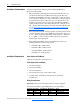
Wiring Specifications
Important:All power, I/O and signal wiring is customer supplied.
All wire to be Stranded, copper, 600V/105 °C (194 °F) insulation.
Terminal(s) Description Max. Wire Size Min. Wire Size Torque
L, N Power 10 AWG 22 AWG 1.0 N•m (9.0 lb•in)
GND Ground 6 AWG 16 AWG 2.3 N•m (20.4 lb•in)
– I/O and Signal 12 AWG 22 AWG 0.6…0.8 N•m (4.5…7.1 lb•in)