
Energy Saving Package Instruction Manual

C-12 FanMaster Screens and Field Descriptions
Allen-Bradley® FanMaster™ Energy Saving Package Installation Manual - Publication FANM-IN001B-EN-P – December, 2009 PN-65329
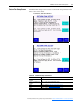
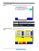
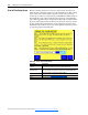
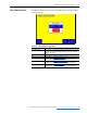
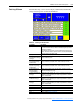
Proof of Flow Setup Screen
The Proof of Flow Setup screen is used to set the torque current level at
which the drive will run the supply fan at the minimum speed. The existing
proof of flow sensor (flow switch or pressure sensor) may not provide
accurate proof of flow at a reduced fan speed. FanMaster will detect flow by
monitoring the torque current required by the supply fan at the minimum
speed. If the supply fan drive is not delivering 50% of this current threshold,
the proof of flow output turns off. This screen allows the system to capture
the 50% threshold by monitoring the current supplied to the motor at the
minimum fan speed. This screen is also used to run the fan motor(s) in order
to verify the proper rotation direction.
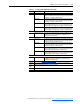
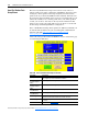
Table C.K Proof of Flow Screen Fields
Field Name Description
Steps 1…4 & Auto Set
Trq Limit
Sets the minimum torque current level at which the drive will run the supply
fan and runs drive and fan motor(s) for rotation direction test.
Proof of Flow Torq Limit
(Amps/Percent)
The minimum torque current level required to run the supply fan motor.
This field displays the current level in percent for PowerFlex 70EC drives
only. All other drives current values display in Amps.
AHU Press to view the Air Handler Unit Diagram Screen
.
Back Press to view the Cooling and Heating Setup Screen
.
Next Press to view the Data Collection Screen
.