FanMaster™ Energy Saving Package Installation Manual (v2.
Important User Information Solid state equipment has operational characteristics differing from those of electromechanical equipment. Safety Guidelines for the Application, Installation and Maintenance of Solid State Controls (Publication SGI-1.1 available from your local Rockwell Automation sales office or online at http:// www.rockwellautomation.com/literature) describes some important differences between solid state equipment and hard-wired electromechanical devices.
Table of Contents Important User Information . . . . . . . . . . . . . . . . . . . . . . . . . . . . . . . . . . . . . . . . . . . . . . . 1-2 Preface General Information Who Should Use This Manual . . . . . . . . . . . . . . . . . . . . . . . . . . . . . . . . . . . . . . . . . . . . . What is Contained in this Manual. . . . . . . . . . . . . . . . . . . . . . . . . . . . . . . . . . . . . . . . . . . Manual Conventions . . . . . . . . . . . . . . . . . . . . . . . . . . . . . . . . . . . . . . . . . . .
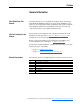
2 Fan Communication Setup Screen. . . . . . . . . . . . . . . . . . . . . . . . . . . . . . . . . . . . . . . . . . Cooling and Heating Setup Screen . . . . . . . . . . . . . . . . . . . . . . . . . . . . . . . . . . . . . . . . . Proof of Flow Setup Screen . . . . . . . . . . . . . . . . . . . . . . . . . . . . . . . . . . . . . . . . . . . . . . . Data Collection Screen . . . . . . . . . . . . . . . . . . . . . . . . . . . . . . . . . . . . . . . . . . . . . . . . . .
Preface General Information Who Should Use This Manual Use this manual if you are responsible for installing and/or operating the Allen-Bradley® FanMaster™ Energy Saving Package (FanMaster). You must have a thorough understanding of installation and operation of HVAC units, Building Automation Systems (BAS) and electrical circuitry and components in order to successfully install this product.
p-2 General Information Reference Materials Rockwell Automation publications are available on the internet at www.rockwellautomation.com/literature.
Chapter 1 FanMaster Overview FanMaster Description FanMaster provides a means for improving the energy efficiency of Constant Air Volume HVAC units. Constant Air Volume HVAC units typically draw in room air and mix it with a small amount of outside air. This mixed air is forced by a fan through heating and/or cooling elements to provide supply air back to the room at a temperature that makes up for heating or cooling lost to the surrounding environment.
1-2 FanMaster Overview FanMaster Externally Mounted Components Temperature Sensors Two temperature sensing probes are provided with FanMaster. These probes are essential to FanMaster because the measured difference in temperature between these sensors provides the command signal for the fan speed.
FanMaster Overview 1-3 Pressure Sensor (Optional) In certain applications it may be necessary or desirable to maintain a positive building pressure relative to the outside air. A pressure sensor can be ordered with FanMaster which monitors the differential pressure between the inside and outside air. When the differential pressure is lower than a user specified setpoint, the FanMaster will override to 100% fan speed to try to restore the desired minimum pressure differential.
1-4 FanMaster Overview Fan Starter Current Sensor This device is used only when FanMaster is installed in evaluation mode. The current sensor device is designed such that one wire lead of the existing fan motor passes through its center. The current sensor has a switch that actuates when it senses current flow in the motor wire, indicating that the fan motor has been started by the existing control system.
FanMaster Overview 1-5 Demand Ventilation Mode A second source of energy savings is achieved by FanMaster's Demand Ventilation mode. A typical Constant Air Volume HVAC unit is equipped with a damper that allows a small percentage of outside air to be mixed with the return air, maintaining an adequate CO2 level for the building's occupants. The damper is typically set during installation for a fixed volume of fresh air, adequate for the worst case condition of full occupancy.
1-6 FanMaster Overview Constant Ventilation Mode Constant Ventilation mode can be used in specific applications requiring a relatively constant flow of outside air be maintained for ventilation at all times. This mode is not recommended for most installations as it precludes the savings which may be realized by reducing the quantity of outside air brought into the HVAC system.
FanMaster Overview 1-7 Proportional Heating and Cooling Control Proportional control of heating or cooling is used when the actual amount of heating or cooling applied by the HVAC unit is variable. That is, the heating or cooling element is modulated by a mechanical or electrical valve. The valve modulates how much heating or cooling is provided and is adjusted by the existing control system to meet the actual demand.
1-8 FanMaster Overview Supply Air Low Limit / High Limit Override The supply air limit override setup values allow you to configure FanMaster to run the fan at full speed as the supply air temperature reaches a low or high limit. The default values are suitable for use in most cases. It is desirable to limit the supply air temperature extremes to protect the HVAC equipment. Increasing the fan speed to 100% as the temperature approaches limits will provide this protection.
FanMaster Overview 1-9 Multi-Stage Heating or Cooling Systems If the HVAC system has heating or cooling elements which turn on in more than one step (e.g., low heat or high heat) FanMaster should be configured for proportional control. This will allow the fan to run at minimum speed if the heating and cooling are off. The fan will step to a medium speed at low heating or cooling and step to maximum speed at high heating or cooling.
1-10 FanMaster Overview The data set for each location on the CD contains a diagram and chart, as shown in Figure 1.1 below. The tabulated monthly data in the chart is the data to be entered into the custom user data screen. The data presents the BTU’s per CFM of ventilation air for each month of the year for the selected location. The energy calculator multiplies the average required BTU's per CFM times the estimated CFM ventilation of the HVAC unit.
FanMaster Overview 1-11 Specific Setup Values This section provides additional information for setting up specific FanMaster configuration fields. The values entered in these fields help the energy calculator to perform a more accurate estimate of energy savings and are not used by the basic control algorithm and will not affect actual savings. • Heating Efficiency % - Use the manufacturer’s data sheet for the HVAC unit to determine this efficiency.
1-12 FanMaster Overview • Pressure Low Limit InWC - This value sets the minimum inside vs. outside air pressure. If the differential is below this value (in a negative direction) the fan speed will increase to 100%. The default value of -0.010 means the outside air pressure is just slightly higher than the inside air. If necessary, adjust this value so that the fan only goes into override speed when building doors are opened or if some other factor requires periodic additional airflow.
Chapter 2 FanMaster Installation General Precautions ! ! ! ! ATTENTION: Only qualified personnel familiar with Heating, Ventilating and Air Conditioning (HVAC) systems, adjustable frequency AC drives and associated instrumentation and machinery should plan or implement the installation, start-up and subsequent maintenance of the system. Failure to comply may result in personal injury and/or equipment damage. ATTENTION: The following information is merely a guide for proper installation.
2-2 FanMaster Installation Installation Considerations Installation Requirements Consider and plan for the following when installing FanMaster for integration with an AHU: • The existing BAS control supply fan start/stop signal. Two relays are provided for interfacing to the BAS fan start/stop signal. The relay installed in the FanMaster enclosure accommodates a 120V AC signal. A second relay is shipped loose and accommodates a 24V AC signal.
Outside Air Exhaust Air FANMASTER FAULTED PanelView C600 FANMASTER OVERRIDE OFF ON FanMaster Supply Air Conditioned Space PowerFlex 400, 70EC, 700VC, or 753 AC Drive BAS Start/Stop Control Fan Motor Current Switch (if used) Supply Fan Supply Air Temp Trans Return Air Figure 2.
2-4 FanMaster Installation Installation Install the Instruments on the AHU Refer to Figure 2.1 on page 2-3 the for guidance on instrument locations. Important: Instrument cables must be no longer than 3200 m (10499 ft) for 4…20 mA signals using a minimum of 20 AWG wire and 200 m (656 ft) for digital signals using a minimum of 20 AWG wire.
FanMaster Installation 2-5 Damper Position Indicator Switch • If your installation does not use constant ventilation, install the damper position indicator switch with the following considerations: – The damper position switch must be installed in a location that allows the switch to detect the damper position (e.g., on the damper actuator crank arm).
2-6 FanMaster Installation This publication provides specific steps for interconnecting the drive and FanMaster. For detailed drive spacing, lifting, mounting, grounding and other detailed installation instructions, refer to the following publications: PowerFlex 400 AC Drive • PowerFlex 400 AC Drive Packages for Fan & Pump Applications Installation Manual, publication 22C-IN002. PowerFlex 70EC AC Drive • PowerFlex 70 Adjustable Frequency AC Drive Installation Instructions, publication 20A-IN009.
FanMaster Installation 2-7 Install the FanMaster Enclosure Environment • The NEMA/UL Type 1 enclosure is rated for an operating temperature range of 0°…40°C (32°…104°F). Important: The NEMA/UL Type 1 enclosure must be mounted in a clean, dry location. Contaminants such as oils, corrosive vapors and abrasive debris must be kept out of the enclosure. These enclosures are intended for indoor use primarily to provide a degree of protection against contact with enclosed equipment.
2-8 FanMaster Installation Figure 2.3 NEMA/UL Type 1 FanMaster Enclosure Dimensions Dimensions are in mm and (inches). PanelView C600 580 (22.84) FANMASTER OVERRIDE OFF ON FANMASTER FAULTED 495.3 (19.50) 247.65 (9.75) Ø10.4 (0.41) Through Mounting Holes Typ. 6 Places 42.40 (1.67) 508.00 (20.00) Side View 533.40 (21.00) 253.24 (9.
FanMaster Installation Figure 2.4 2-9 NEMA/UL Type 4 FanMaster Enclosure Dimensions Dimensions are in mm and (inches). 610.00 (24.00) 291.00 (11.47) 572.00 (22.50) 19.00 (0.75) 231.00 (9.10) Clearance for Ø 9.5 (3/8) Mounting Hardware Typ. 4 Places 18.00 (0.72) 203.00 (8.00) 646.00 (25.45) 673.00 (26.50) 610.00 (24.
2-10 FanMaster Installation FanMaster Enclosure Weights Enclosure NEMA/UL Type 1 NEMA/UL Type 4 Enclosure Only Enclosure and Packaging 21.0 kg (46 lb) 26.3 kg (58 lb) 36.3 kg (80 lb) 41.7 kg (92 lb) Lifting Instructions The dimensions and weights provided above must be taken into consideration when lifting and mounting the enclosure. Use the proper equipment to safely lift and hold the weight of the enclosure while mounting.
FanMaster Installation 2-11 Wire the FanMaster and Drive (if Installed) Refer to the FanMaster Diagrams contained in Appendix B for wiring and connection details. ! ATTENTION: Do not route signal and control wiring with power wiring in the same conduit. This can cause interference with operation. Failure to observe this precaution could result in damage to, or destruction of, the equipment. 1.
2-12 FanMaster Installation Important: For each installed instrument, allow for the appropriate cable length necessary to reach the FanMaster I/O terminals in the enclosure. Refer to Wiring Specifications on page 2-2 for control wire size. 4. Wire the supply air temperature transmitter according to the manufacturer’s instructions, route through the appropriate conduit (if used) and connect the control wires to terminals 100, 102, 123 and 124 on TB2 in the FanMaster enclosure. 5.
FanMaster Installation 2-13 PowerFlex 70EC, 700VC or 753 Drive Important: When installing a PowerFlex 753 drive, the 20-COMM-H communication adapter requires the 20-750-20COMM carrier option module. Important: Leave the 20-COMM-H adapter rotary node address switches set to “00” and set the network protocol switch to “RTU”. 2 2 3 4 1 0 5 9 6 7 8 3 4 1 0 5 9 6 8 7 RTU N2 P1 Important: The communication cable maximum length should not exceed 500 m (1,640 ft). a.
2-14 FanMaster Installation 10. Connect the normally open (“Run”) contact in the supply fan drive to FanMaster to indicate that the supply fan motor is running. – For PowerFlex 400 drives, connect terminal R4 on the drive relay TB to terminal 135 on TB2 in FanMaster and terminal R5 on the drive relay TB to terminal N on TB2 in FanMaster. Note: The relay terminal block is on the front of the drive, below the communication adapter.
FanMaster Installation 2-15 14. If the existing fan motor starter provides an auxiliary open or closed contact when the relay is energized, normal operation of the existing control system may not be possible without this contact. Therefore, disconnect the wires from the fan motor started contact and connect it to the appropriate auxiliary contact terminals provided in the FanMaster enclosure. The FanMaster auxiliary contacts actuate when the drive is on and turning the fan.
2-16 FanMaster Installation Outside Air Damper with Electric Actuator (0…10V DC or 4…20 mA) The existing outside air damper has an electric actuator with a 0…10V DC or 4…20 mA control signal: i. Remove the (+) control wire from the actuator (+) terminal and connect it to terminal 155 on TB2 in the FanMaster enclosure. ii. Wire terminal 153 on TB2 to the actuator (+) terminal. iii.
FanMaster Installation 2-17 16. (Optional - required when using the constant ventilation option rather than the default demand ventilation option.) If FanMaster will be used to control the outside air damper for constant ventilation control, connect the damper position control wires to the appropriate terminals on the drive. Important: The analog output terminal used on the drive must be set for a 4…20 mA signal only.
2-18 FanMaster Installation 21. (Optional) If a dry contact output from FanMaster that closes on a high CO2 level is required for connection to a BAS CO2 alarm device, connect the signal wires from the CO2 alarm annunciation device to terminals 117 and 118 on TB2 in the FanMaster enclosure. 22.
Chapter 3 FanMaster Configuration and Start Up This chapter contains the steps necessary to configure and start up FanMaster. Typical values are provided as defaults where applicable. The default values may not be valid for your installation and, if left unchanged, may affect the calculated energy savings results. Verify all values in Table 3.A on page 3-2 prior to completing the configuration procedures.
3-2 FanMaster Configuration and Start Up Gather and Record Data Gather the following data in order to successfully configure and start up the FanMaster. Record the actual data for your installation in the table below and save the table for your records. Table 3.
FanMaster Configuration and Start Up Step Data Required Default Value 49d The percentage of full speed that the drive will run the supply fan when the temperature difference is at or above the maximum value when cooling the conditioned space. 100 49a The difference in temperature between the mixed air and supply air at or below which the drive will run the supply fan at the minimum speed when heating the conditioned space.
3-4 FanMaster Configuration and Start Up Important: Verify that all steps in Chapter 2 - FanMaster Installation are complete and that the 20-COMM-H communication adapter is installed, connected and that the rotary switches are set correctly before completing the FanMaster configuration procedure below. Configure the FanMaster 1. Apply power to FanMaster and apply power to the drive(s), if installed. The PanelView HMI will boot up (this may take 2…3 minutes). 2.
FanMaster Configuration and Start Up 3-5 3. Read the notes on the screen and press “OK”. The Dashboard screen displays. 4. Press “Next”. The Air Handler Unit Diagram screen displays.
3-6 FanMaster Configuration and Start Up 5. Press “Setup”. You are prompted to enter a user name and password. 6. Press in the “User” field and, using the keypad, type “s”. 7. Press in the “Password” field and, using the keypad, type “258” and press “Enter” ( ). The first Setup screen displays. Note: If the PanelView is inactive for more than 15 minutes, you will be logged out and returned to a non-secured screen. When you press “Setup” again, you be required to log back into the setup screens.
FanMaster Configuration and Start Up 3-7 8. Select the city with the climate profile closest to the installation location (refer to City Climate Profiles on page A-3 for a list of city values). Press the up and down arrows ( ) below the list to scroll to and choose a city. City names are listed alphabetically, in order of North America (U.S. then Canada), Europe, Central and South America, and Asia. Press Enter ( highlighted. ) to apply your selection.
3-8 FanMaster Configuration and Start Up 10. Press the value to the right of the “Supply Fan FLA” field and enter the supply fan motor rated full load amps. Note: At this point, any warning messages about an incorrect AHU unit CFM value may display and can be disregarded until all values for the supply and return fans have been entered. Press OK. 11. Press the value to the right of the “Unit CFM” field and enter the air flow volume for the AHU.
FanMaster Configuration and Start Up 3-9 20. Press “Next”. The Setup Date and Time screen displays. 21. Press the value next to the “Set Month” field and enter the current month (1-12). 22. Press the value next to the “Set Day” field and enter the current date. 23. Press the value next to the “Set Year” field and enter the current year (in the format ccyy). 24. Press the value next to the “Set Hour” field and enter the current hour (military, 24 hour, format). 25.
3-10 FanMaster Configuration and Start Up 27. Press “Next”. The second Setup screen displays. Evaluation Unit Install Only Permanent Install Only 28. If you have installed an evaluation unit, continue with step 29 below. If your installation contains a drive, select the Drive Type used for the AHU (see Available Drive Types on page A-5 for a description of each available drive). Press the up and down arrows ( ) below the list to scroll to and choose a type. Press Enter ( highlighted.
FanMaster Configuration and Start Up 3-11 29. If the AHU uses a proportional heating system (heating source level is varied), continue with the next step. If the AHU uses a two-state (heating is on or off) heating system, press “Heating Prop” so that “Heating 2-State” displays. 30. If the AHU uses a proportional cooling system (cooling source level is varied), continue with the next step.
3-12 FanMaster Configuration and Start Up 34. Press “Next”. The third Setup screen displays. 35. If the AHU does not have a heating system, press “No” next to “Does AHU Have Mech Heating?”. “Mech Heat” changes to display “No Mech Heat”. 36. If the AHU does not have a cooling system, press “No” next to “Does AHU Have Mech Cooling?”. “Mech Cool” changes to display “No Mech Cool”. 37.
FanMaster Configuration and Start Up 3-13 41. If a CO2 sensor is installed, press the value next to the “CO2 Alarm Setpoint ppm” and enter the CO2 parts per million (ppm) at which the an alarm will display on the PanelView screen, the fault indicator lamp on the front of the unit will turn on and the FanMaster Faulted signal will be set to “Faulted”, indicating that the high CO2 level threshold has been exceeded. 42. Press Next. The Supply Fan Setup screen displays. PowerFlex 753 Drives Only 43.
3-14 FanMaster Configuration and Start Up Important: If, after completing the steps below, the following alarm message displays, “Drive Parameter Write Failed”, do the following: • Verify all communication wiring between the drive(s) and FanMaster. • Verify the parameter settings for PowerFlex 70EC, 700VC or 753 drives as instructed below. – Setting the Parameters in a PowerFlex 70EC or 700VC Drive (below). – Setting the Parameters in a PowerFlex 753 Drive on page 3-15.
FanMaster Configuration and Start Up 3-15 Setting the Parameters in a PowerFlex 753 Drive Important: When removing power from the drive(s) as directed in the steps on this screen, verify that the drive is fully de-energized by waiting until the HIM module LED display is off. a. If a Device Conflict message displays, press the button below the “FIX” text displayed on the screen, then press the button below the “ENTER” text displayed on the screen to confirm. b.
3-16 FanMaster Configuration and Start Up q. Press the button below the “PAR #” text on the screen. r. Press the button below the down arrow on the screen (not the blue down arrow) to view parameter 32 [RTU Param Mode]. s. Press the button below the “ENTER” text on the screen. t. Press the button below the “EDIT” text on the screen. u. Press the button below the up arrow on the screen (not the blue up arrow) to select “32 Bit Parameters”. v. Press the button below the “ENTER” text on the screen. w.
FanMaster Configuration and Start Up 3-17 44. Press “Next”. If a return fan is not installed, the Fan Communication Setup screen displays - continue with step 47. For return fan setup, continue with step 45 below. PowerFlex 753 Drives Only 45. Read and complete the tasks in steps 3 and 4 on the Return Fan Setup screen to set the return fan parameters in the drive to the correct values. For PowerFlex 400 drives, complete the tasks on the Return Fan Setup screen only.
3-18 FanMaster Configuration and Start Up 46. Press “Next”. The Fan Communication Setup screen displays. 47. Read and complete the tasks in step 5 (if a return fan is installed) or 3 (if a return fan is not installed) on this screen to test the communication link between the drive(s) and the fan(s). A message(s) displays to indicate if communications are working properly. Refer to Chapter 4 Troubleshooting for more information if communications are not working properly. 48. Press “Next”.
FanMaster Configuration and Start Up 3-19 Note: When in cooling mode, the supply fan speed will typically be set based on the difference in temperature (Delta-T) between the mixed air and supply air (as illustrated, using default values, in Figure 3.1 and Figure 3.2 below) unless the supply air temperature exceeds the low limit override (is less than the default value of 45° F).
3-20 FanMaster Configuration and Start Up 49. Below “Cooling Setup”, enter the following values: a. Press the value next to “Delta-T Min” and enter the difference in temperature between the mixed air and supply air at or below which the drive will run the supply fan at the minimum speed (set in the corresponding “VFD Output Min” field) when cooling the conditioned space.
FanMaster Configuration and Start Up 3-21 Note: When in heating mode, the supply fan speed will typically be set based on the difference in temperature (Delta-T) between the mixed air and supply air (as illustrated, using default values, in Figure 3.3 and Figure 3.4 below) unless the supply air temperature exceeds the high limit override (is greater than the default value of 155° F).
3-22 FanMaster Configuration and Start Up 50. Below “Heating Setup”, enter the following values: a. Press the value next to “Delta-T Min” and enter the difference in temperature between the mixed air and supply air at or below which the drive will run the supply fan at the minimum speed (set in the corresponding “VFD Output Min” field) when heating the conditioned space.
FanMaster Configuration and Start Up 3-23 52. The “Supply Air High Limit” field, below “SA High Limit Override” is used to set a supply air high temperature limit above which FanMaster will run the supply air fan at full speed (100%) to avoid overheating the heating system. Press the value next to “Supply Air High Limit” and enter the supply air high temperature limit at which FanMaster will command the supply fan to run at full speed. 53. Press “Next”.
3-24 FanMaster Configuration and Start Up 55. When the test is complete, press “OK” and then “Next”. The Data Collection screen displays. 56. In order to finalize the configuration, you will clear any data currently stored in the logs and then put FanMaster into service collecting new data. Press “Clear Logs” on the Data Collection screen. A message displays to confirm that you want to delete the data stored in the log. Press “Yes”. 57. Press “Start Collecting”. “Stopped” will change to “Collecting”.
FanMaster Configuration and Start Up 3-25 60. Verify that the temperature transmitters and CO2 sensor readings are acceptable: – Insert a calibrated thermometer into the air duct where the mixed air temperature transmitter is installed and compare the reading to the value displayed in the “MAT (°F)” field on the Air Handler Unit Diagram screen. The value in the “MAT (°F)” field should be within +/- 5% of the of the value on the thermometer.
3-26 FanMaster Configuration and Start Up View Detailed Data Log Information You can view detailed historical energy saving data logged by the FanMaster. 1. On the Air Handler Unit Diagram screen, press “Data Log”. The first Data Log View screen displays. 2. To select a specific month for which you want to view data, press the up and down arrows ( ) below the list of months to scroll to and choose a month. Press Enter ( highlighted. ) to apply your selection.
FanMaster Configuration and Start Up 3-27 Start or Stop Data Collection To start or stop collecting data: 1. On the Air Handler Unit Diagram screen, press “Data Log”. The first Data Log View screen displays. 2. Press “Logging Control”. The Data Collection screen displays. • To start collecting data, press “Start Collecting”. “Stopped” will change to display “Collecting”. • To stop collecting data, press “Stop Collecting”. “Collecting” will change to display “Stopped”.
3-28 FanMaster Configuration and Start Up Clear the Data Logs and Collect Data Important: Clearing the data logs will delete all historical energy savings data. This task should only be performed when you have completed the entire FanMaster configuration task and need to begin collecting new data. To clear the logs and begin collecting data: 1. On the Air Handler Unit Diagram screen, press “Data Log”. The first Data Log View screen displays. 2. Press “Logging Control”.
Chapter 4 Troubleshooting This chapter contains information on troubleshooting the FanMaster. Important: Power must be supplied and circuit breaker CB1 in the FanMaster enclosure must be set to “ON” in order for the PanelView terminal and MicroLogix controller to run. If the PanelView screen or display on the MicroLogix controller is dark (off), set CB1 to “OFF” and check the power source and wiring to the unit. Once the power source and wiring has been verified, set CB1 to “ON”.
4-2 Troubleshooting FanMaster Alarms An alarm banner displays on the PanelView terminal to indicate an alarm condition. The alarm banner displays on the screen until “Ack” (Acknowledge) is pressed. Clearing the alarm banner does not remove the alarm condition. Refer to the table below for a complete list of alarms and possible actions.
Troubleshooting Alarm Pressure Out Of Range Return Fan Comm Fault Return Fan Drive Fault Supply Fan Comm Fault Supply Fan Drive Fault Supply Air Temperature High Supply Air Temperature Low Description One of the following has occurred: • The polarity of the device wiring is incorrect. • The pressure hose is crimped or blocked. • The pressure level is above or below the operating range (OOR) of the device. 4-3 Possible Action(s) • Verify that the wiring is correct.
4-4 Troubleshooting Alarm Outside Air Damper Signal Out Of Range Mixed Air Temperature Low CO2 Level Above Setpoint Setup Values At Defaults / Perform Setup Per User Manual Description One of the following has occurred: • The polarity of the device wiring is incorrect. • The outside air damper signal is above or below the operating range (OOR) of the device. Possible Action(s) • Verify that the wiring is correct. • Check the damper position switch wiring for damage and replace if necessary.
Appendix A Specifications and City Climate Profiles Drives and FanMaster Specifications PowerFlex Drives Category Specification PowerFlex 400 AC Drive: Ratings: 200…240V AC: 2.2…37 kW 3…50 Hp 12…88 A PowerFlex 70EC Drive: Ratings: 200…240V AC: 0.37…18.5 kW 0.5…25 Hp 2.2…78.2 A PowerFlex 700VC Drive: Ratings: 200V AC: 0.5…100 Hp 2.5…260 A 240V AC: 0.5…100 Hp 2.2…260 A PowerFlex 753 Drive: Ratings: 400V AC: 0.75…250 kW 2.1…456 A 400…480V AC: 2.2…250 kW 3…350 Hp 4.8…460 A – 400…480V AC: 0.37…37 kW 0.
A-2 Specifications and City Climate Profiles Category Inputs and Outputs Instrumentation Optional Instrumentation Specification Inputs: • Supply Air Temp. @ 4…20 mA = 0°…100°C (32°…212°F) • Mixed Air Temp. @ 4…20 mA = 0°…100°C (32°…212°F) • CO2 @ 4…20 mA = 0…2000 ppm • Damper Position Switch (when not using constant vent.
Specifications and City Climate Profiles City Climate Profiles A-3 The tables below include the cities (by geographical area) that are pre-loaded in the FanMaster database and are selected on the first Setup screen.
A-4 Specifications and City Climate Profiles North America - United States City, State Albuquerque, NM Anchorage, AL Arcata/Eureka, CA Astoria/Clatsop, OR Billings/Logan, MT Birmingham, AL Boise, ID Boston/Logan, MA Brownsville, TX Buffalo, NY Burlington, VT Charleston, SC Charleston/Kanawha, WV Chattanooga/Lovell, TN Chicago/O’Hare, IL Columbia, SC Cut Bank, MT Dayton/James M Cox, OH Denver/Stapleton, CO City, State Des Moines, IA Detroit City, MI Dodge City (Awos), KS Duluth, MN Ely/Elland Field, NV El
Specifications and City Climate Profiles A-5 Available Drive Types Selection: PF400 Keypad Only Description: PowerFlex 400 drive with an integral keypad with Hand-Off-Auto (HOA) mode, no HOA switch, no speed potentiometer (pot) and no bypass. PF400 HOA & Speed Pot. No PowerFlex 400 drive with an integral keypad, HOA Bypass switch, speed pot, and no bypass.
A-6 Specifications and City Climate Profiles Notes: Allen-Bradley® FanMaster™ Energy Saving Package Installation Manual - Publication FANM-IN001B-EN-P – December, 2009 PN-65329
Appendix B FanMaster Diagrams Drawing Index Schematics (FanMaster w/Drive) Drawing Figure B.1 FanMaster (w/Drive) Schematic Diagram Sheet 1A Figure B.2 FanMaster (w/Drive) Schematic Diagram Sheet 1B Figure B.3 FanMaster (w/Drive) Schematic Diagram Sheet 2A Figure B.4 FanMaster (w/Drive) Schematic Diagram Sheet 2B Page B-2 B-3 B-4 B-5 Schematics (FanMaster Evaluation Unit) Drawing Figure B.5 FanMaster Evaluation Unit Schematic Diagram Sheet 1A Figure B.
B-2 FanMaster Diagrams Figure B.
FanMaster Diagrams Figure B.2 100 FanMaster (w/Drive) Schematic Diagram Sheet 1B MicroLogix 1100 Base I/O Slot 0 Inputs (From Sheet 1A) A (+24V DC) Supply Fan Running (To Sheet 2B) CR1-1 E 11 14 103 TB2 Line 100 TB2 Signal 105 Damper in Econ.
B-4 FanMaster Diagrams Figure B.3 (From Sheet 1B) (From Sheet 1B) B B 100 TB2 100 Supply Air Temp. 123 102 Shld 124 100 Mixed Air Temp.
FanMaster Diagrams Figure B.
B-6 FanMaster Diagrams Figure B.
FanMaster Diagrams Figure B.6 100 FanMaster Evaluation Unit Schematic Diagram Sheet 1B MicroLogix 1100 Base I/O Slot 0 Inputs (From Sheet 1A) A (+24V DC) B-7 DC Com (From Sheet 1A) A 102 (0V DC) 102 I/0 TB2 Line 100 Damper in Econ.
B-8 FanMaster Diagrams Figure B.7 (From Sheet 1B) (From Sheet 1B) B B 100 TB2 100 Supply Air Temp. 123 102 Shld 124 100 Mixed Air Temp.
FanMaster Diagrams Figure B.8 Interconnect Diagram for PowerFlex 400 Drive - Sheet 1 TB1 TB2 34 36 161 162 Drive TB TB2 Enclosure Bypass Enable PowerFlex 400 R4 Drive Running (See Note 4) RJ45 Signal = 4-20 mA Drive TB + 15 – 14 RS-485 135 Signal = 120V AC R5 Supply Fan Drive Optional Position Command to Damper B-9 N AK-U0-RJ45-TB2P - RJ45 to TB Adapter (Typ.
B-10 FanMaster Diagrams Figure B.9 Interconnect Diagram for PowerFlex 70EC Drive - Sheet 1 PowerFlex 70EC 24 Drive Running FanMaster TB2 Drive I/O TB 135 Signal = 120V AC 25 N Fan Running Input Supply Fan Drive TB3 20-COMM-H TB Optional Position Command to Damper RS-485 cable GND Signal = 4-20 mA SHIELD SHLD COM COM B B Drive I/O TB + 23 A.O. – 22 A.O.
FanMaster Diagrams B-11 Figure B.10 Interconnect Diagram for PowerFlex 700VC Drive - Sheet 1 PowerFlex 700VC TB2 Drive I/O TB Drive Running 16 135 Signal = 120V AC 15 N FanMaster Fan Running Input Supply Fan Drive TB3 20-COMM-H TB Optional Position Command to Damper GND Signal = 4-20 mA SHIELD SHLD COM COM B B Drive I/O TB + 7 A.O. 1 – 6 A.O.
B-12 FanMaster Diagrams Figure B.11 Interconnect Diagram for PowerFlex 753 Drive - Sheet 1 PowerFlex 753 Drive Running FanMaster TB2 Drive TB2 R0NO 135 Signal = 120V AC R0C N Fan Running Input Supply Fan Drive TB3 20-COMM-H TB Optional Position Command to Damper GND Signal = 4-20 mA + – SHIELD SHLD COM COM B B Drive TB1 Ao0+ A.O. 0 Ao0– A.O.
FanMaster Diagrams B-13 Figure B.12 Interconnect Diagram - Sheet 2 From Sheet 1 From Sheet 1 A FanMaster A TB2 Supply Air Temperature Sensor Power Out Mixed Air Temperature Sensor Power 100 123 102 124 Signal = 4-20 mA Com Supply Air Temp. Sensor +24V DC Supply Air Temp. Sensor Signal Input Supply Air Temp. Sensor Common Shield TB2 Out 100 125 102 126 Signal = 4-20 mA Com Mixed Air Temp. Sensor +24V DC Mixed Air Temp. Sensor Signal Input Mixed Air Temp.
B-14 FanMaster Diagrams Figure B.
FanMaster Diagrams B-15 Figure B.
B-16 FanMaster Diagrams Figure B.
FanMaster Diagrams B-17 HTR1 Figure B.
B-18 FanMaster Diagrams Notes: Allen-Bradley® FanMaster™ Energy Saving Package Installation Manual - Publication FANM-IN001B-EN-P – December, 2009 PN-65329
Appendix C FanMaster Screens and Field Descriptions This chapter contains a description of the information contained on each FanMaster screen. The screens are listed in order of appearance as you complete the configuration procedures.
C-2 FanMaster Screens and Field Descriptions Dashboard Screen The Dashboard screen provides a quick view of the energy savings performance of FanMaster. The green, yellow and red color bands on the gauges identify the most desirable to least desirable readings, respectively. Table C.A Dashboard Screen Fields Field Name Avg. Fan Speed % Avg.
FanMaster Screens and Field Descriptions Air Handler Unit Diagram Screen C-3 The Air Handler Unit Diagram screen provides an overview of a typical AHU configuration and current FanMaster readings. Table C.B Air Handler Unit Diagram Screen Fields Field Name CO2 ppm Return Fan % MAT (°F) SAT (°F) (ECON) Supply Fan % Dashboard AHU System Status Data Log Setup Description Current CO2 level in parts per million (ppm). Current return fan percentage of full speed (if installed and configured).
C-4 FanMaster Screens and Field Descriptions Setup Screen #1 The first Setup screen is used to enter data required to configure the FanMaster for your installation. Table C.C Setup Screen #1 Fields Field Name (City, State/Country) Supply Fan HP Supply Fan FLA Unit CFM Does AHU Have A Return Fan? Return Fan HP Return Fan FLA Elect Cost $ per kWh Nat Gas Cost $/MMBTU Heating Efficiency % Damper Minimum Pos % (Coolant Type) User City Next Description City and State location selection.
FanMaster Screens and Field Descriptions C-5 Setup Date and Time Screen The Setup Date and Time screen is used to enter the current date and time. Table C.D Set Date and Time Screen Fields Field Name Set Month Set Day Set Year Set Hour Set Minute (date and time) Press to Accept AHU Back Next Description Current month (numeric). Current Day of the month. Current year. Current hour (military format). Current minute. Displays the time entered in the time and date fields.
C-6 FanMaster Screens and Field Descriptions Setup Screen #2 The second Setup screen is used to enter data required to configure the FanMaster for your installation. This screen is different for evaluation unit versus units installed with a drive. This configuration is completed at the factory. Evaluation Unit Install Only Permanent Install Only Table C.E Setup Screen #2 Fields Field Name Drive Type Description Type of drive installed.
FanMaster Screens and Field Descriptions Field Name CO2 AHU Back Next Setup Screen #3 C-7 Description CO2 sensor (CO2) or no CO2 sensor (No CO2) installed selection. Press to view the Air Handler Unit Diagram Screen. Press to view the Setup Date and Time Screen. Press to view the Setup Screen #3. The third Setup screen is used to enter data required to configure the FanMaster for your installation. Table C.
C-8 FanMaster Screens and Field Descriptions Supply Fan Setup Screen The Supply Fan Setup screen is used to set the supply fan parameters in the drive to the correct values. PowerFlex 400, 70EC and 700VC Drives PowerFlex 753 Drives Only Table C.G Supply Fan Setup Screen Fields Field Name Step 1…Set Supply Fan Defaults Step 2…Set Supply Fan Params AHU Back Next Description Used to set the supply fan to the default values. Used to set the supply fan parameter values.
FanMaster Screens and Field Descriptions Return Fan Setup Screen C-9 The Return Fan Setup screen is used to set the return fan parameters in the drive to the correct values. PowerFlex 400, 70EC and 700VC Drives PowerFlex 753 Drives Only Table C.H Return Fan Setup Screen Fields Field Name Step 3…Set Return Fan Defaults Step 4…Set Return Fan Params AHU Back Next Description Used to set the return fan to the default values. Used to set the return fan parameter values.
C-10 FanMaster Screens and Field Descriptions Fan Communication Setup Screen The Fan Communication Setup screen is used to test the communication link between the supply and return (if installed) drive and fan. Table C.I Fan Communication Setup Screen Fields Field Name Step 5 (or Step 3) …Test VFD Comms AHU Back Next Cooling and Heating Setup Screen Description Used to test the communication link between the drives and fans.
FanMaster Screens and Field Descriptions Table C.J C-11 Cooling and Heating Setup Screen Fields Heading Field Name Cooling Setup Delta-T Min Delta-T Max VFD Output Min VFD Output Max Description The difference in temperature between the mixed air and supply air at and below which the drive will run the supply fan at the minimum speed when cooling the conditioned space.
C-12 FanMaster Screens and Field Descriptions Proof of Flow Setup Screen The Proof of Flow Setup screen is used to set the torque current level at which the drive will run the supply fan at the minimum speed. The existing proof of flow sensor (flow switch or pressure sensor) may not provide accurate proof of flow at a reduced fan speed. FanMaster will detect flow by monitoring the torque current required by the supply fan at the minimum speed.
FanMaster Screens and Field Descriptions Data Collection Screen C-13 The Data Collection screen is used to start and stop data collection and/or clear the data logs. Table C.L Data Collection Screen Fields Field Name Start/Stop Collecting Clear Logs AHU Back Done (Data Log) Description Starts or stops data logging. When “Start Collecting” is pressed, “Stopped” changes to “Collecting”. When “Stop Collecting” is pressed, “Collecting” changes to “Stopped”.
C-14 FanMaster Screens and Field Descriptions User City Weather Data Setup Screen The User City Weather Data Setup screen is used to create and save a climate profile for use in the configuration of FanMaster when none of the existing city climate profiles in the setup adequately match the climate profile of the city in which the FanMaster unit is installed. You must enter the appropriate data in all fields on the screen for each month in the year in order to successfully create a climate profile.
FanMaster Screens and Field Descriptions Data Log #1 Screen C-15 The first Data Log screen is used to display detailed monthly energy and savings data calculated by FanMaster for up to five years running. Table C.N Data Log #1 Screen Fields Field Name Description January, February, March Month selection. Choose the month for which you want to view data using … the up or down and Enter arrow buttons. Note: When the current month is selected, data displayed represents the month to date values.
C-16 FanMaster Screens and Field Descriptions Data Log #2 Screen The second Data Log screen is used to display additional detailed monthly energy and savings data calculated by FanMaster. Table C.O Data Log #2 Screen Fields Field Name Description January, February, March Month selection. Choose the month for which you want to view data. … Choose the month for which you want to view data using the up or down and Enter arrow buttons.
FanMaster Screens and Field Descriptions Data Log #3 Screen C-17 The third Data Log screen is used to display additional detailed monthly energy and savings data calculated by FanMaster. Table C.P Data Log #3 Screen Fields Field Name Description January, February, March Month selection. Choose the month for which you want to view data. … Choose the month for which you want to view data using the up or down and Enter arrow buttons.
C-18 FanMaster Screens and Field Descriptions System Status Screen The System Status screen is used to display additional detailed monthly energy and savings data collected by the FanMaster. Table C.
Appendix D FanMaster Application Firmware Upgrades Complete all steps in this appendix to upgrade your FanMaster MicroLogix 1100 and PanelView terminal application firmware. Note: You may be required to upgrade the PanelView operating system firmware to the latest available prior to upgrading the FanMaster PanelView application firmware. The PanelView operating system must be version 1.11 or higher in order to run the FanMaster PanelView application version 2.00.
D-2 FanMaster Application Firmware Upgrades 4. Open the FanMaster enclosure and remove the existing memory module from the MicroLogix 1100 controller’s processor. Pull memory module straight out of chassis. ESC OK 5. Install the new memory module. Verify that the module is fully seated in place. The new application firmware will be installed on the next power cycle.
FanMaster Application Firmware Upgrades Upgrade the FanMaster PanelView Application Firmware D-3 1. Insert the USB thumb drive containing the FanMaster application firmware into the USB port on the back of the PanelView terminal. USB host port. FAULT B T T- R R- S Back View 2. Press “Setup” on the “Air Handler Unit Diagram” screen. You are prompted to enter a user name and password. 3. Press in the “User” field and, using the keypad, type “s”. 4.
D-4 FanMaster Application Firmware Upgrades 5. Press “Next” until the Cooling and Heating Setup screen displays. 6. Press “PNLVW CONFIG”. The PanelView screen displays “Loading…” for a short time and then the Main configuration screen displays.
FanMaster Application Firmware Upgrades D-5 7. Press “File Manager” on the left side of the screen. The File Manager screen displays. 8. Press the down arrow next to “Source” until “USB” displays.
D-6 FanMaster Application Firmware Upgrades 9. Select the file in the list that has the new PanelView application firmware and press “Copy” below the list. The Copy File screen displays. 10. Press “Copy Application” below the “From” field. The Copy To screen displays. Verify that “Internal” displays in the “To:” field before proceeding.
FanMaster Application Firmware Upgrades D-7 11. Press “Copy”. A message displays indicating that the copy was successful. Press “OK”. The File Manager screen displays. 12. Verify that “Internal” is displayed in the “Source” field, select the new PanelView application file in the list, using the blue arrow keys, and press “Set As Startup” below the list. The Startup Application screen displays.
D-8 FanMaster Application Firmware Upgrades 13. Press “Change Startup Application” to confirm your choice. The File Manager screen displays again. 14. Press “Run” below the list. “Loading…” displays for a short time. The Important Notice screen displays. 15. Verify that you the correct firmware version displays in the lower left corner of the screen. The firmware version also displays in the lower left corner of the Dashboard screen. Restart FanMaster with the New Application Firmware 1.
Index A Drive Types A-5 Air Handler Unit Diagram screen C-3 Application Firmware Upgrades D-1, D-3 E Estimated Savings Calculator Operation 1-6 B Bypass Switch Operation A-5 F Fan Communication Setup screen C-10 C Fan Speed Reduction 1-4 Carbon Dioxide Sensor Installation Considerations 1-2 Fan Starter Current Sensor Installation Considerations 1-4 City Climate Data Applying 1-9 Fan Starter Hard-Wired Interconnection Installation Considerations 1-4 City Climate Profile Create C-14 FanMaster Ala
Index-2 FanMaster Screens C-1 Air Handler Unit Diagram screen C-3 Cooling and Heating Setup C-10 Dashboard screen C-2 Data Collection C-13 Data Log #1 C-15 Data Log #2 C-16 Data Log #3 C-17 Fan Communication Setup C-10 Proof of Flow Setup C-12 Return Fan Setup C-9 Setup #1 C-4 Setup #2 C-6 Setup #3 C-7 Setup Date and Time C-5 Supply Fan Setup C-8 System Status C-18 User City Weather Data Setup C-14 FanMaster Startup 3-1 Installation Considerations 2-2 Drive 2-5 FanMaster Enclosure 2-7 Instruments 2-4 Requ
Index-3 Proportional Heating and Cooling Control Applying 1-7 Publications, Reference p-2 R Systems Without Outside Air Dampers Applying 1-8 T Temperature Sensors Installation Considerations 1-2 Reference Material p-2 Torque Specifications 2-2 Required Installation Data 3-2 Two State Heating or Cooling Control 1-6 Required Tools 2-2 Restarting FanMaster with New Application Firmware D-8 Return Fan Comm Fault alarm 4-3 Return Fan Drive Fault alarm 4-3 Return Fan Setup screen C-9 S Schematic Diagram
Index-4 Allen-Bradley® FanMaster™ Energy Saving Package Installation Manual - Publication FANM-IN001B-EN-P – December, 2009 PN-65329
U.S. Allen-Bradley Drives Technical Support - Tel: (1) 262.512.8176, Fax: (1) 262.512.2222, Email: support@drives.ra.rockwell.com, Online: www.ab.com/support/abdrives www.rockwellautomation.com Power, Control and Information Solutions Headquarters Americas: Rockwell Automation, 1201 South Second Street, Milwaukee, WI 53204 USA,Tel: (1) 414.382.2000, Fax: (1) 414.382.