
Design Considerations Reference Manual User guide


Rockwell Automation Publication ENET-RM002C-EN-P - May 2013 91
Predict System Performance Chapter 5
Determine If System Has Sufficient Bandwidth
to Meet Application Requirements
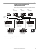
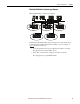
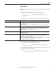
Based on the system requirements, the initial network diagram is shown below:
Chassis 1
• 1756-L73 Controller
• 1756-EN2T Module 1
• One Produced Tag
PanelView Plus Terminal
Workstation
with RSView
To Company
Intranet
Chassis 4
• 1756-EN2T Module 4
• Three Analog I/O Modules
• Three Digital I/O Modules
Chassis 7
• 1756-EN2T Module 7
• Three Analog I/O Modules
• Three Digital I/O Modules
Chassis 5
• 1756-EN2T Module 5
• Three Analog I/O Modules
• Three Digital I/O Modules
Chassis 8
• 1756-EN2T Module 8
• Three Analog I/O Modules
• Three Digital I/O Modules
Chassis 6
• 1756-EN2T Module 6
• Three Analog I/O Modules
• Three Digital I/O Modules
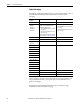
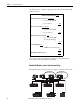
IMPORTANT: Each chassis with three analog and three digital I/O modules, that is, chassis 4…8, uses these connections:
• Three direct connections (one for each analog I/O module in the chassis)
• One rack connection (one for all digital I/O modules in the chassis)
Switch
Chassis 2
• 1756-L73 Controller
• 1756-EN2T Module 2
• One Consumed Tag
Chassis 3
• 1756-L73 Controller
• 1756-EN2T Module 3
• One Consumed Tag