Reference Manual Ethernet Design Considerations
Important User Information Solid-state equipment has operational characteristics differing from those of electromechanical equipment. Safety Guidelines for the Application, Installation and Maintenance of Solid State Controls (publication SGI-1.1 available from your local Rockwell Automation sales office or online at http://www.rockwellautomation.com/literature/) describes some important differences between solid-state equipment and hard-wired electromechanical devices.
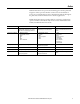
Summary of Changes This manual contains new and updated information. Changes throughout this revision are marked by change bars, as shown to the right of this paragraph. New and Updated Information This table contains the changes made to this revision.
Summary of Changes Notes: 4 Rockwell Automation Publication ENET-RM002C-EN-P - May 2013
Table of Contents Preface Studio 5000 Environment . . . . . . . . . . . . . . . . . . . . . . . . . . . . . . . . . . . . . . . . 10 Additional Resources . . . . . . . . . . . . . . . . . . . . . . . . . . . . . . . . . . . . . . . . . . . . . 11 Chapter 1 EtherNet/IP Overview Network Protocols . . . . . . . . . . . . . . . . . . . . . . . . . . . . . . . . . . . . . . . . . . . . . . . CIP . . . . . . . . . . . . . . . . . . . . . . . . . . . . . . . . . . . . . . . . . . . . . . . . . . . . . . . . .
Table of Contents Spanning Tree Protocol (STP) and Rapid STP (RSTP) . . . . . . . . . . EtherChannel Protocol . . . . . . . . . . . . . . . . . . . . . . . . . . . . . . . . . . . . . . . Flex Links Protocol . . . . . . . . . . . . . . . . . . . . . . . . . . . . . . . . . . . . . . . . . . . Resilient Ethernet Protocol (REP) . . . . . . . . . . . . . . . . . . . . . . . . . . . . . Device-level Ring (DLR) . . . . . . . . . . . . . . . . . . . . . . . . . . . . . . . . . . . . . .
Table of Contents Estimate Maximum Input or Output Times for CIP Connections . Example: Predict System Performance . . . . . . . . . . . . . . . . . . . . . . . . . . . . . Determine If System Has Sufficient Bandwidth to Meet Application Requirements . . . . . . . . . . . . . . . . . . . . . . . . . . . . Explicit Messaging. . . . . . . . . . . . . . . . . . . . . . . . . . . . . . . . . . . . . . . . . . . . EtherNet/IP Module Serving as a Scanner . . . . . . . . . . . . . . . . . . . . . .
Table of Contents Notes: 8 Rockwell Automation Publication ENET-RM002C-EN-P - May 2013
Preface Rockwell Automation uses open network technology for seamless, plant-wide integration. These open networks share a universal set of communication services. As a result, information can be communicated seamlessly throughout the plant and to and from the Internet for e-business applications. Each Rockwell Automation network is ideal for a wide range of applications, operates with devices manufactured by various vendors, and shares data with industry-standard information networks.
Preface Studio 5000 Environment The Studio 5000 Engineering and Design Environment combines engineering and design elements into a common environment. The first element in the Studio 5000 environment is the Logix Designer application. The Logix Designer application is the rebranding of RSLogix 5000 software and continues to be the product to program Logix5000™ controllers for discrete, process, batch, motion, safety, and drive-based solutions.
Preface These documents and websites contain additional information concerning related products from Rockwell Automation. Additional Resources Table 1 - ODVA Resources Resource Description http://www.odva.org/ Accesses the Open DeviceNet Vendors Association (ODVA) website. http://www.odva.org/default.aspx?tabid=54 Accesses the CIP Advantage website.
Preface Notes: 12 Rockwell Automation Publication ENET-RM002C-EN-P - May 2013
Chapter 1 EtherNet/IP Overview Topic Page Network Protocols 14 Configuration Requirements 15 EtherNet/IP Modules in a Control System 19 Bridge across Networks 20 The EtherNet/IP protocol is a multi-discipline, control and information platform for use in industrial environments and time-critical applications. The EtherNet/IP network uses standard Ethernet and TCP/IP technologies and an open, application-layer protocol called the Common Industrial Protocol (CIP).
Chapter 1 EtherNet/IP Overview Network Protocols On the most basic level, Ethernet is a wire or cable that connects computers and peripheral modules so that they can communicate. The actual wire used for the network is referred to as the network medium. Beyond the physical medium, all Ethernet networks support protocols that provide data transfer and network management capability.
EtherNet/IP Overview Configuration Requirements Chapter 1 All devices on Ethernet communicate by using the Ethernet address for the device. This address is sometimes referred to as the hardware address or Media Access Controller (MAC) address. The hardware address is a unique, six-byte address, which is embedded in the circuitry of every device on an Ethernet network. Every vendor of Ethernet products obtains their own unique address range.
Chapter 1 EtherNet/IP Overview Each node on the same physical network must have an IP address of the same class and must have the same network ID. Each node on the same network must have a different local address (host ID), thus giving it a unique IP address. IP addresses are written as four-decimal integers (0...255) separated by periods where each integer gives the value of one byte of the IP address. For example, the following 32-bit IP address is written as 130.0.0.
EtherNet/IP Overview Chapter 1 Gateway Address A gateway connects individual physical networks into a system of networks. When a node needs to communicate with a node on another network, a gateway transfers the data between the two networks. The following figure shows gateway G connecting Network 1 with Network 2. A 128.1.0.1 128.1.0.2 Network 1 G B C 128.2.0.1 128.2.0.3 128.2.0.2 Network 2 When host B with IP address 128.2.0.
Chapter 1 EtherNet/IP Overview Subnet Mask Subnet addressing is an extension of the IP address scheme. It enables a site to use a single net ID for multiple physical networks. Routing outside of the site continues by dividing the IP address into a net ID and a host ID via the IP class. Inside a site, the subnet mask is used to redivide the IP address into a custom net ID portion and host ID portion.
EtherNet/IP Overview Chapter 1 The following diagram shows how EtherNet/IP communication modules can fit into a control system.
Chapter 1 EtherNet/IP Overview Bridge across Networks Some EtherNet/IP communication modules support the ability to bridge or route communication through devices, depending on the capabilities of the platform and communication devices. You have a bridge when you have a connection between communication devices on two networks.
Chapter 2 Ethernet Infrastructure Components Topic Page Topologies 22 Media 24 Hubs 25 Repeaters 25 Media Converters 26 Bridges 26 Routers and Gateways 27 Switches 28 The topology and cable layout of the Ethernet network is part of the physical layer. Ethernet systems require various infrastructure components to connect individual network segments.
Chapter 2 Ethernet Infrastructure Components Ethernet networks are laid out in point-to-point configurations with one cable for each device. Ethernet networks have active infrastructures that rely on switches. You can design a network with individual switch devices and devices with embedded switch technology.
Ethernet Infrastructure Components Chapter 2 The EtherNet/IP embedded switch technology offers alternative network topologies by embedding switches into the end devices themselves. Table 5 - Topologies with Embedded Switch Technology Topology Description Device-level ring (DLR)—embedded switch A DLR network is a single-fault tolerant ring network intended for the interconnection of automation devices. This topology is also implemented at the device level. No additional switches are required.
Chapter 2 Media Ethernet Infrastructure Components The actual wire used for the network is referred to as the physical media. Generally, shorter cable runs are less susceptible to EMI (electromagnetic interference) and RFI (radio-frequency interference) from electrical circuits, motors, and other machinery.
Ethernet Infrastructure Components Hubs Chapter 2 Hubs are multiport repeaters. They are based on older technology, which has been largely replaced by network switches at Layer 2, but they are still used as network diagnostic tools to analyze network traffic: • A hub is at the center of a star topology. • Hubs can connect together with a variety of media as a backbone between hubs. • A hub broadcasts everything it receives on any channel out all other channels.
Chapter 2 Ethernet Infrastructure Components Media Converters Media converters let you mix fiber and copper (twisted-pair) cables in the same system. Use a switch to mix media: • Physical layer devices offer no buffering or advanced diagnostic features. • Physical layer devices are easily overrun by an EtherNet/IP system (no buffering = lost data). • Layer 2 devices have buffering, QoS, and other management features.
Ethernet Infrastructure Components Routers and Gateways Chapter 2 Routers and gateways use the network portion of IP addresses to identify the location of networks. A routing table lets a device know from which port to transmit a message, so the message can get to a particular network. If that network is not directly attached to the device, it forwards the message to the next gateway or router in the path for further routing. Routing Table Network 10.17.10.0 10.10.10.0 Port 1 2 Default Gateway 10.10.
Chapter 2 Ethernet Infrastructure Components Switches provide determinism and throughput required for control applications. Industrial-rated switches are recommended for connecting computers and other devices to each other and to higher-level networks in the network reference architecture.
Ethernet Infrastructure Components Chapter 2 Unmanaged versus Managed Switches Unmanaged switches are relatively inexpensive and simple to set up, but they do not provide any management capabilities, security, or diagnostic information. Therefore, they are difficult to troubleshoot.
Chapter 2 Ethernet Infrastructure Components Full-duplex Mode Ethernet is based on Carrier Sense Multiple Access/Collision Detect (CSMA/ CD) technology. This technology places all nodes on a common circuit so they can all communicate as needed. The nodes must handle collisions (multiple devices talking at the same time) and monitor their own transmissions so that other nodes have transmission time. The data transmission mode you configure determines how devices transmit and receive data.
Chapter 3 Ethernet Infrastructure Features Topic Page Transmission Packets 32 Transmission Protocols 35 Network Address Translation 38 Virtual LANs and Segmentation 42 Quality of Service (QoS) 45 Resiliency 46 Internet Group Management Protocol (IGMP) 55 Port Security 56 Device Commissioning 58 When you use the EtherNet/IP network for time-critical control, there are several features available in switches that are required or recommended.
Chapter 3 Ethernet Infrastructure Features Transmission Packets Data is transmitted over the EtherNet/IP network in packets. There are transmission methods for transporting data on the network. Packet Type Destination Description Unicast A single node Unicast connections are point-to-point transmissions between a source node and destination node on the network. A frame is sent to a single destination.
Ethernet Infrastructure Features Chapter 3 Limit the amount of broadcast and multicast traffic on the supervisory control network: • Eliminating unwanted traffic reduces the load on devices, switches, and the network. • Eliminating unnecessary incoming broadcast traffic also minimizes network load. It is important to prevent network traffic from coming into the supervisory control (level 2) and manufacturing operations (level 3) network from other levels.
Chapter 3 Ethernet Infrastructure Features Frames Use multicast frames in these situations: • Redundancy applications • Communication with more than one destination Multicast is more efficient than sending multiple, unicast streams to multiple nodes. • Video streaming To Plant Network Switch or Router Layer 2 Switch Controller (consumer) Layer 2 Switch I/O (producer) You must use unicast communication if the transmission routes through a Layer 3 device.
Ethernet Infrastructure Features Chapter 3 Multicast Address Limit In multicast communication, EtherNet/IP interfaces support a maximum of 32 devices that transmit multicast. EXAMPLE An Ethernet adapter that produces data uses a unique multicast address for each I/O connection. EXAMPLE A Logix controller that produces tags uses a unique multicast address for each produced tag. The multicast address limit is independent of the connection limit for a device.
Chapter 3 Ethernet Infrastructure Features If you replace a Rockwell Automation EtherNet/IP communication module with a new module, the new module has a different MAC ID. The ARP cache entries in other devices are now invalid because the MAC ID corresponding to the module's IP address has changed. This can cause a delay in reestablishing communication with the replacement module. The delay varies depending on the module and the network configuration in use.
Ethernet Infrastructure Features Chapter 3 The DNS server refers to its table and sends back an IP address for the requested name. Once the client device receives the IP address for a name, it stores it in its own table so it does not have to ask for the IP address every time. The device still sends an ARP request if it needs to decode the IP address into a hardware address. 1756 Controller I have IP address 130.151.3.4 DNS Server 1734 POINT I/O DNS Table Name IP Address Controller 130.151.3.
Chapter 3 Ethernet Infrastructure Features Network Address Translation Network address translation (NAT) enables a single device to act as an agent between the public network (commonly the plant network) and the private network (machine network). This facilitates communication between a group of computers with preset IP addresses on a private network by mapping each preset IP address to a valid IP address on the public network.
Ethernet Infrastructure Features Chapter 3 Supported NAT Topologies Figure 3 - Switch-level Ring (REP) with Stratix 5700 Switch Plant Network Stratix 5700 with NAT Logix Controller PanelView POINT I/O PowerFlex Drive Figure 4 - Star with 9300-ENA Device CompactLogix™ 5370 Controller PanelView Plus Stratix 2000 9300-ENA Kinetix 350 Rockwell Automation Publication ENET-RM002C-EN-P - May 2013 39
Chapter 3 Ethernet Infrastructure Features Figure 5 - Star with Stratix 5700 Switch Plant Network Stratix 5700 with NAT PanelView Logix Controller POINT I/O PowerFlex Drive Figure 6 - Redundant Star with Stratix 5700 Switch Plant Network Stratix 5700 with NAT PanelView Logix Controller 40 POINT I/O Rockwell Automation Publication ENET-RM002C-EN-P - May 2013 PowerFlex Drive
Ethernet Infrastructure Features Chapter 3 Figure 7 - Star with Device-level Ring Plant Network 9300-ENA or Stratix 5700 with NAT 1783-ETAP 1783-ETAP Logix Controller PanelView POINT I/O Kinetix 5500 Drive Rockwell Automation Publication ENET-RM002C-EN-P - May 2013 41
Chapter 3 Ethernet Infrastructure Features A virtual LAN (VLAN) is a switched network segmented on a functional application or organizational basis rather than a physical or geographical basis. Switches filter destination MAC addresses and forward VLAN frames to ports that serve the VLAN only to which the traffic belongs. A VLAN consists of several end systems. These systems are either hosts or network equipment, such as switches and routers, that are members of a single logical broadcast domain.
Ethernet Infrastructure Features Chapter 3 A security policy can call for limiting access of factory floor personnel, such as a vendor or contractor, to certain areas of the production floor, such as a functional area. Segmenting these areas into distinct VLANs greatly assists in the application of these types of security considerations. VLAN 10 VLAN 102 VLAN 42 All level 0…2 devices that need to communicate multicast I/O between each other must be in the same LAN.
Chapter 3 Ethernet Infrastructure Features VLAN Trunking Trunking enables a VLAN to span multiple switches. VLAN 102 802.1 Q Trunk VLAN 102 VLAN 42 VLAN 42 VLAN 20 VLAN 20 VLANs and Segmentation Guidelines Configure separate VLANs for different work cells or areas of your plant. Configure one VLAN for all data traffic relevant to one particular area or cell zone. Because 80…90% of traffic is local to one cell, this is the optimal design.
Ethernet Infrastructure Features Chapter 3 Quality of service determines how packets are marked, classified, and treated based on traffic type. Rockwell Automation EtherNet/IP devices prioritize traffic internally. Implementing QoS at the switch level adds another level of prioritization. QoS does not increase bandwidth—QoS gives preferential treatment to some network traffic at the expense of others. Quality of Service (QoS) Not all network traffic can be treated equally.
Chapter 3 Ethernet Infrastructure Features QoS Guidelines Follow these guidelines with QoS: • Manage the output queues based on application needs. Schedule precision and motion control packets in the highest priority queue. • QoS gives preferential treatment to Industrial Automation and Control System Network traffic at the expense of other network traffic. • QoS is integrated into the Stratix 8000 and Stratix 8300 switch configurations.
Ethernet Infrastructure Features Chapter 3 Resiliency Protocols • Spanning Tree Protocol (STP), Rapid STP (RSTP), Multiple Instance STP (MSTP) – Stratix 8000 and Stratix 8300–MSTP default – Rapid Per VLAN Spanning Tree Plus (rPVST+); Cisco Technology • Resilient Ethernet Protocol (REP); Cisco Technology • EtherChannel Link Aggregation Control Protocol (LACP); IEEE • Flex Links; Cisco Technology • Device-level ring; topology option Resiliency Protocol Mixed Vendor Ring Redundant Star Network Convergence
Chapter 3 Ethernet Infrastructure Features Spanning Tree Protocol (STP) and Rapid STP (RSTP) Spanning Tree Protocol (STP) prevents loops on the network that occur when there is more than one open path active at once on the network. The convergence rate can take up to 50 seconds. Rapid Spanning Tree Protocol (RSTP) is designed for faster network convergence and eliminates the forwarding delay on point-to-point links by using explicit handshaking protocol.
Ethernet Infrastructure Features Chapter 3 EtherChannel Protocol The EtherChannel protocol combines multiple physical switch ports into one logical connection to increase bandwidth through load balancing, as well as physical connection redundancy. This protocol groups several physical Ethernet links to create one logical Ethernet link for the purpose of providing fault-tolerance and high-speed links between switches, routers, and servers.
Chapter 3 Ethernet Infrastructure Features Flex Links Protocol The Flex Links protocol provides link-level, physical redundancy in redundant star topologies.
Ethernet Infrastructure Features Chapter 3 Resilient Ethernet Protocol (REP) REP operates on chain of bridges called segments. A port is assigned to a unique segment. A segment can have up to two ports on a given bridge. REP is built in to Stratix 8000 and Stratix 8300 switches.
Chapter 3 Ethernet Infrastructure Features Segments can be wrapped into a ring. Identification of edge ports requires additional configuration. CC Blocking Blocking YY AA XX Forwarding Forwarding BB CC Forwarding Forwarding YY AA XX BB Link Failure Link Failure Device-level Ring (DLR) The DLR protocol is a layer 2 protocol that provides link-level, physical redundancy that provides network convergence in the 1…3 ms range for simple automation device networks.
Ethernet Infrastructure Features Chapter 3 A DLR network is a single-fault tolerant network. Network traffic is managed to make sure critical data is delivered in a timely manner.
Chapter 3 Ethernet Infrastructure Features Network convergence includes the following: • After failure detection, ring supervisor unblocks blocked port • Network configuration is now a linear topology • Fault location is readily available via diagnostics ControlLogix Controller Active Ring Supervisor Forwarding Stratix 8000 IE Switch Forwarding Link Failure 1783-ETAP POINT I/O Disrtributed I/O ArmorPOINT I/O Distributed I/O POINT I/O Disrtributed I/O ArmorPOINT I/O Distributed I/O Once ring is r
Ethernet Infrastructure Features Internet Group Management Protocol (IGMP) Chapter 3 The IGMP is a communication protocol used to manage the membership of IP multicast groups. Much of EtherNet/IP implicit (I/O) messaging uses IP multicast to distribute I/O control data, which is consistent with the CIP produced/consumer model. Without IGMP, switches treat multicast packets the same as broadcast packets. Multicast packets are re-transmitted to all ports.
Chapter 3 Ethernet Infrastructure Features Port Security The switch has dynamic and static methods for limiting the MAC addresses (MAC IDs) that can access a given port. Dynamic Secure MAC Address (MAC ID) With Stratix 8000 and Stratix 8300 switches, the Smartport roles have a maximum number of MAC IDs that can use that port. For example, the Smartport role ‘Automation Device’ sets up the port for a maximum of one MAC ID.
Ethernet Infrastructure Features Chapter 3 Security Violations In the event of a security violation with a Stratix 8000 or Stratix 8300 switch, one of these situations occurs: • The maximum number of secure MAC addresses that have been configured for a port have been added to the address table, and a station whose MAC address is not in the address table attempts to access the interface. • An address learned or configured on one secure interface is seen on another secure interface in the same VLAN.
Chapter 3 Ethernet Infrastructure Features Device Commissioning There are multiple methods for assigning IP addresses. Switches on the product, such as thumbwheels, push buttons, or HIM modules, provide a static address that survives power cycles. Stratix switches support DHCP port allocation. DHCP port allocation is a hybrid solution for IP addressing because it provides easy device replacement, but is topology dependant. 58 Option Description Static Devices are hard-coded with an IP address.
Chapter 4 EtherNet/IP Protocol Topic Page Connections 59 EtherNet/IP Network Specifications 66 Packets Rate Capacity 69 Requested Packet Interval (RPI) 70 Messaging 71 CIP Safety 73 CIP Sync 74 Integrated Motion on an EtherNet/IP Network 76 Connectivity to IT 77 The EtherNet/IP protocol is standard Ethernet and standard IP technologies with standard CIP technology at the application layer.
Chapter 4 EtherNet/IP Protocol This graphic shows how connections are layered on each other when data is transferred over the EtherNet/IP network. CIP Connection Types Your decisions when configuring your application determine the parameters of these connections. Connected Unconnected Connected CIP Connection Message Types Explicit Implicit CIP Connection You do not execute any tasks to establish these connections.
EtherNet/IP Protocol Chapter 4 These example applications describe how connections are used. EXAMPLE I/O Connections A Logix5000 controller has five CIP I/O connections to modules in a remote chassis and all of these connections are through the same local 1756-EN2T module and the same remote 1756-EN2T module.
Chapter 4 EtherNet/IP Protocol TCP Connections TCP connections are used for all EtherNet/IP communication and are established before one device on the network transmits data to one or more devices on the network. EtherNet/IP communication modules use one TCP connection for each IP address to which the module is connected. TCP connections are automatically established before CIP connections because you can establish CIP connections only over a TCP connection.
EtherNet/IP Protocol IMPORTANT Chapter 4 CIP connections are further defined by these additional connection parameters: • CIP Connection Message Types • CIP Connection Types CIP Connection Message Types CIP connections use one of the following CIP connection message types: • Implicit • Explicit Implicit connections are time critical in nature. This includes I/O and produced/consumed tags.
Chapter 4 EtherNet/IP Protocol Table 10 - CIP Connections with Implicit and Explicit Messages CIP Connection Type As Used with Implicit Messages As Used with Explicit Messages Connected The following events occur: 1. A connection is established between devices. 2. Data is transferred between devices. 3. The connection remains open for future data transmission.
EtherNet/IP Protocol Chapter 4 Nodes on an EtherNet/IP Network IMPORTANT This section applies to only CompactLogix 5370 controllers. For most applications, proceed to Table 12 on page 66 for network specifications. CompactLogix 5370 controllers use the number of Ethernet nodes to stay within their capacity for the number of connections. These controllers have limits on the number of nodes they support in the I/O configuration within your controller project.
Chapter 4 EtherNet/IP Protocol EtherNet/IP Network Specifications Table 12 - EtherNet/IP Network Specifications Cat. No.
EtherNet/IP Protocol Chapter 4 Table 13 - EtherNet/IP Network Specifications Cat. No. Media Support Twisted Pair (1) Produced/Consumed Tags Fiber Number of Unicast Available in Multicast Tags, Max RSLogix 5000 Software Socket Integrated Motion Services on the EtherNet/IP Network Axes Duplicate IP Detection (starting revision) 1734-AENT, 1734-AENTR Yes(2) No N/A Version 18.02.00 or later No N/A Revision 2.x - 1734-AENT Revision 3.
Chapter 4 EtherNet/IP Protocol Table 14 - Additional ControlLogix EtherNet/IP Communication Module Specifications Cat. No. Series Firmware Revision RSLogix 5000 RSLinx Software Packet Rate Capacity (packets/ second)(2) Support for Integrated Motion Software Version Version Extended on the EtherNet/IP (4) I/O HMI/MSG Environment Network Axes 1756-ENBT Any Any 8.02.00 or later 1756-EN2F A 2.x 15.02.00 or later 3.6 or later 2.30 or later 5000 2.51 or later 10,000 (1) 25,000 18.02.
EtherNet/IP Protocol Packets Rate Capacity Chapter 4 Beginning with firmware revision 3.x for ControlLogix EtherNet/IP communication modules, packet rate capacity is increased. IMPORTANT Connection size impacts a module’s increased packet rate capacity gained with firmware revision 3.x or later. Smaller connections are processed faster than larger connections. Larger connections can affect the increased packet rate capacity obtained with firmware revision 3.x or later.
Chapter 4 EtherNet/IP Protocol Upgrade to Latest Firmware Revision All ControlLogix EtherNet/IP communication modules must be upgraded to firmware revision 3.x or later to increase their packet rate capacity. You can upgrade your module’s firmware regardless of series. Download the latest firmware revisions at the Rockwell Automation technical support website. http://support.rockwellautomation.
EtherNet/IP Protocol Messaging Chapter 4 The EtherNet/IP network supports both time-critical (implicit) and non timecritical (explicit) message transfer services of CIP. Exchange of time-critical messages is based on the producer/consumer model where a transmitting device produces data on the network and many receiving devices can consume this data simultaneously. Implicit Messages Implicit messages are time critical in nature. This includes I/O and produced/ consumed tags.
Chapter 4 EtherNet/IP Protocol Explicit Messages Explicit connections are non-time critical and are request/reply in nature. Executing a MSG instruction or executing a program upload are examples of explicit connections. Explicit refers to basic information (such as source address, data type, or destination address) that is included in every message. Each request is typically directed at a different data item.
EtherNet/IP Protocol Chapter 4 CIP Safety is an extension to the application layer that provides a set of highly integrated safety services that leverage the underlying communication stacks of the standard CIP networks to transport data from a source to a destination. CIP Safety is certified to be compliant with the functional safety standard IEC 61508 up to safety integrity level (SIL) 3.
Chapter 4 EtherNet/IP Protocol CIP Sync CIP Sync defines time synchronization services for CIP. Time synchronization on the EtherNet/IP network is a method to synchronize clocks across devices on the network. In a synchronized application, there is a single time master and multiple time slaves. For example, a ControlLogix controller can be configured to act as the time master and other ControlLogix modules, connected via EtherNet/IP communication modules, serve as the time slaves.
EtherNet/IP Protocol Chapter 4 Typical time synchronized applications include the following: • Input time stamping – Events and alarms – Sequence of Events recording – First fault detection • Time scheduled outputs • Integrated motion on EtherNet/IP drive synchronization • Distributed motion control CIP Sync a time synchronization extension to the application layer can help solve these application requirements.
Chapter 4 EtherNet/IP Protocol Integrated Motion on an EtherNet/IP Network Integrated motion on an EtherNet/IP network sets the EtherNet/IP networking technology apart from the other industrial Ethernet networks. EtherNet/IP modules with integrated motion on the EtherNet/IP network combine the requirements of deterministic real-time motion control applications with standard unmodified Ethernet that provides full compliance with the Ethernet standards IEEE 802.3 and TCP/IP.
EtherNet/IP Protocol Chapter 4 While IT and controls engineers are often managed separately and given separate job performance goals, those goals are beginning to align because the availability of information is crucially important in both roles. Some companies are beginning to form hybrid groups and hire individuals with experience in both areas to form policies, guidelines, and procedures for design and maintenance of a common network architecture.
Chapter 4 EtherNet/IP Protocol Notes: 78 Rockwell Automation Publication ENET-RM002C-EN-P - May 2013
Chapter 5 Predict System Performance Topic Page System Prediction Goals 80 Performance Calculations 83 Example: Predict System Performance 90 This chapter describes how to predict the performance of your EtherNet/IP network-based control system and how to enhance that performance IMPORTANT This chapter explains how to calculate system performance with data from your system in specific equations.
Chapter 5 Predict System Performance System Prediction Goals You allocate the bandwidth of your EtherNet/IP communication module between two types of messaging. Messaging Type Description Explicit messaging Explicit messages are connections that do not use an RPI. Some examples of explicit messaging include the following: • MSG instructions • HMI communication • Studio 5000 uploads and downloads Implicit messaging Implicit messages are connections that use an RPI.
Predict System Performance Chapter 5 Part One: Determine If System Has Sufficient Bandwidth to Meet Application Requirements Part One To determine if your system has sufficient bandwidth to fulfill the requirements of the application, complete the following steps. Start Step 1: Draw Your System 1.
Chapter 5 Predict System Performance Part Two: Predict Maximum input or Output Times for CIP Connections A CIP connection is an efficient communication path used for high performance. The following are basic types of CIP connections: • Rack-optimized • Input or output data • Produced tag A CIP connection is bi-directional. During every RPI, each end of a connection initiates a packet of information. A packet of information represents a connection.
Predict System Performance Chapter 5 Logix5000 controllers use packets per second and the number of connections for predicting system performance. However, CompactLogix 5370 controllers use the number of Ethernet nodes to stay within their capacity for the number of connections. Performance Calculations CompactLogix 5370 Controller Example As shown in the illustration below, the 1769-L16ER-BB1B controller supports a maximum of four nodes.
Chapter 5 Predict System Performance While you can use the EtherNet/IP node count to select a CompactLogix 5370 controller for your network requirements, most applications use three sets of calculations to determine performance: • Identify and Count Connections • Calculate Packets/Second • Estimate Maximum Input or Output Times for CIP Connections ControlLogix Controller Example This example control system includes these connections: • The 1756-L73 controller in the local chassis producing one tag that t
Predict System Performance Chapter 5 Identify and Count Connections Use your design to identify and count the total number of these connections for each EtherNet/IP communication module in your system. Performance prediction is done on a CIP connection basis. This table describes how to count connections for an EtherNet/IP communication module, regardless of whether it is in a local or remote chassis.
Chapter 5 Predict System Performance Calculate Packets/Second All EtherNet/IP communication modules have a packet rate capacity, that is, maximum number of packets/second it can send. You must calculate the number of packets/second that each EtherNet/IP communication module in the control system is sending when predicting system performance.
Predict System Performance Chapter 5 Use this table to count the total packets/second sent for each EtherNet/IP communication module in the example system shown on page 84.
Chapter 5 Predict System Performance Estimate the Fastest RPI The fastest RPI for an EtherNet/IP communication module is calculated with this formula: RPI(Fastest) = (2 x connections)/pps IMPORTANT It is not necessary to operate at the fastest RPI. Example One A 1756-EN2T module, firmware revision 3.6 or later, supports 25,000 pps. If there are only 40 connections that are all at the same RPI, the fastest RPI is the following: RPI(Fastest) = (2 x 40)/25,000 = 3.
Predict System Performance Chapter 5 Estimate Maximum Input or Output Times for CIP Connections System response is dependent on several factors. These are the dominant factors: • RPI value • Number of implicit CIP connections. To simplify, the response time of a connection can be approximated with only the RPI.
Chapter 5 Predict System Performance Example: Predict System Performance This example ControlLogix system has the following components: IMPORTANT The information in the remainder of this section shows how to compute system performance with ControlLogix controllers.
Predict System Performance Chapter 5 Determine If System Has Sufficient Bandwidth to Meet Application Requirements Based on the system requirements, the initial network diagram is shown below: Chassis 2 • 1756-L73 Controller • 1756-EN2T Module 2 • One Consumed Tag Chassis 1 • 1756-L73 Controller • 1756-EN2T Module 1 • One Produced Tag Chassis 3 • 1756-L73 Controller • 1756-EN2T Module 3 • One Consumed Tag Workstation with RSView To Company Intranet Switch Chassis 4 • 1756-EN2T Module 4 • Three Analog
Chapter 5 Predict System Performance Explicit Messaging The RSView® and PanelView Plus messages are explicit messages. Reserve 10% of the bandwidth of the EtherNet/IP communication module for explicit messaging. EtherNet/IP Interface Total Bandwidth 10% Reserve for Explicit Messaging 1756-ENBT 5000 pps 500 pps 1756-EN2F 1756-EN2T 1756-EN2TR 1756-EN2TXT 1756-EN3TR The pps for these modules depends on the module’s series and firmware revision.
Predict System Performance Chapter 5 EtherNet/IP Module Serving as a Scanner EtherNet/IP module 1 functions as a scanner. 1756-EN2T Module 1 EtherNet/IP module 1, in the chassis with the main controller, must perform these tasks: • Communicate with five remote I/O chassis.
Chapter 5 Predict System Performance Fill in the worksheet for this module as follows.
Predict System Performance Chapter 5 EtherNet/IP Modules Functioning as Adapters EtherNet/IP modules 4…8 function as adapters. 1756-EN2T Module 4 1756-EN2T Module 7 1756-EN2T Module 5 1756-EN2T Module 6 1756-EN2T Module 8 Each EtherNet/IP module functioning as an adapter in an I/O chassis, that is, 1756-EN2T EtherNet/IP communication modules 4…8 in the example on page 91, has these connections: • One rack-optimized connection for digital I/O modules in its chassis.
Chapter 5 Predict System Performance For example, use the worksheet in Appendix A for each of the five EtherNet/IP modules as follows.
Predict System Performance Chapter 5 Each of these controllers consumes one produced tag at an RPI = 20 ms. Either of these EtherNet/IP modules uses these connections. EtherNet/IP Module ID: 2 or 3 Produced Tag Connections 0 = (1 + connections)/RPI for each produced tag = N/A Consumed Tags 1 tag @ 20 ms = 2/RPI for each consumed tag = 2/20 ms = Total Packets Per Second 100 100 The total of 100 pps is well within the 1756-EN2T/A module’s, firmware revision 2.003, remaining bandwidth of 9000 pps.
Chapter 5 Predict System Performance Estimate the Maximum Input or Output Times for CIP Connections Calculate the worst-case, maximum input (I/O to controller) or output (controller to I/O) times for CIP connections in your system.
Predict System Performance Chapter 5 Refine Estimates To further increase the accuracy of these times, include considerations for system delays. For a Rack-optimized Connection, to the RPI, add these delays: TMAX (Rack-optimized) = input filter + RPI + transmission + switch + queue See the table for descriptions of delay types with a rack-optimized connection. Type of Delay Description Input Filter Discrete input modules have filters. The default for a 1756 discrete I/O module is 1 ms.
Chapter 5 Predict System Performance Notes: 100 Rockwell Automation Publication ENET-RM002C-EN-P - May 2013
Index A address dynamic secure MAC 56 gateway 17 gateway default 17 resolution protocol (ARP) 35 static secure MAC 56 application bandwidth 81, 90 ARP definition 35 autonegotiation 29 B bandwidth 81, 90 determination 81 explicit message 92 bridge media 26 network communication 20 broadcast 32 C calculate packets per second 86 packets/second 86 system performance 83 capacity packet rate 69 tool 69 CIP connections 62 calculate delays 99 calculate times 98 maximum 82 predict times 82, 89 types 63 definition
Index EtherNet/IP network adapters 95 capacity tool 69 communication modules 19 definition 13 integrated motion 76 module features 66 node count 65 overview 13 protocol 59 scanners 93 specifications 66 example achieve more throughput 97 calculate times for CIP connections 98 consumed tags 96 delay times for CIP connections 99 determine bandwidth 91 RSLinx communication software bridging 20 system performance 90 explicit connections 63 messages 72 messaging 80, 92 messaging bandwidth 92 F firmware revision
Index O overview EtherNet/IP network 13 P packets calculation 86 rate capacity 69 transmission 32 performance calculations 83 system 79 port security 56 produce and consume 61 tags number of multicast 67 producer 61 protocols network 14 transmission 35 Q Qos 45 quality of service (Qos) 45 R rack-optimized connections 62 rapid STP 48 redundant star topology 22 REP 51 repeaters media 25 requested packet interval 70 requirements configuration 15 reserve explicit messaging 92 resiliency 46 Ethernet protocol
Index U UCMM 61 messages 61 unicast 32 default settings 33 unmanaged switches 29 V violations security 57 virtual LAN 42 VLAN 43, 44 trunking 44 104 Rockwell Automation Publication ENET-RM002C-EN-P - May 2013
Rockwell Automation Support Rockwell Automation provides technical information on the Web to assist you in using its products. At http://www.rockwellautomation.com/support, you can find technical manuals, technical and application notes, sample code and links to software service packs, and a MySupport feature that you can customize to make the best use of these tools. You can also visit our Knowledgebase at http://www.rockwellautomation.