
t Owner manual

Rockwell Automation Publication IASIMP-QS016C-EN-P - October 2014 59
Energy Data Collector Configuration Chapter 3
Configure Basic Device Parameters
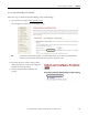
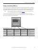
Follow these steps to configure wiring, PT and CT ratios, and nominal system voltage for the PowerMonitor 3000 device.
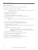
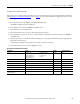
The Basic Device Configuration Parameters
table on page 59 provides a list of basic device configuration parameters and
example settings.
1. Press the Enter key from the PROG.>CONFIGURATION menu.
The BASIC configuration menu is displayed.
2. Press the Enter key to select the WIRING CONFIG. menu.
3. Press the Enter key to access Edit mode.
4. Press the Down Arrow key to select the desired wiring mode parameter.
5. Press the Enter key to write the new value to the PowerMonitor 3000 master module and return to the WIRING
CONFIG menu.
6. Repeat steps 4 and 5 to set the PT Secondary, CT Primary, CT Secondary, and Nominal System Voltage (M6 and
M8 models only) parameters.
The I4 Primary and I4 Secondary parameters are used for neutral metering only.
7. Press the Escape key to return to the Configuration menu.
Basic Device Configuration Parameters
Parameter Range Default Example Settings
Wiring 0 = Delta 3 CT
1 = Delta 2 CT
2 = Direct Delta 3 CT
3 = Direct Delta 2 CT
4 = Open Delta 3 CT
5 = Open Delta 2 CT
6 = Wye
7 = Single Phase
8 = Demo
6 = Wye Wye
PT Primary 1
…10,000,000 480 480 (Volts)
PT Secondary 1
…600 480 480 (Volts)
CT Primary 1
…10,000,000 5 600 (Amps)
CT Secondary 1
…5 5 5 (Amps)
I4 Primary 1
…10,000,000 5
I4 Secondary 1
…55
Nominal System Voltage
(M6 and M8 only)
1
…10,000,000 480 277 (Volts)
(1)
(1) This value is typically line-to-neutral voltage for Wye systems and line-to-line voltage for Delta systems.