
t Owner manual

Rockwell Automation Publication IASIMP-QS016C-EN-P - October 2014 387
Demand Control Chapter 12
Program Overview
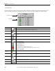
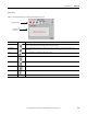
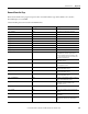
The Demand Control program is organized into eight routines, as shown below.
.
Routine Name Description
MainRoutine Performs the demand control calculations and processes the commands from the faceplate. It also dispatches all of the
subroutines.
SR00_IO_Mapping Used to map the demand control inputs (Load[#].Inp_Status) and outputs (Load[#].Out_Shed) to the corresponding
hardwired I/O point or device level control tag for each load. This routine will need to be customized for each application, as
described on the next page.
SR01_ProcessPM1000 Reads the PowerMonitor 1000 device data and writes the data to the PM tag (UDT).
SR01_ProcessPM5000 Reads the PowerMonitor 5000 device data and writes the data to the PM tag (UDT).
SR02_ProcessLoads Calculates the KWH_Sheddable, processes the timers, determines the inlerlock state, output state, and load status for the
load.
SR03_EvaluateLoads Determines which loads are sheddable and copies the data for the sheddable loads into an array for sorting. This routine is
executed after each shed or restore event and periodically every 10 seconds.
SR04_Sort Sorts the sheddable loads first by priority and then by minutes since shed ascending and stores them in the
Sheddable_Load LIFO array. This array presents the next load to shed as the last element in the array.
SR05_Shed Sets the shed status equal to ‘Shed’ for the next load to shed. Adds the load to the Shed_Load FIFO array. This array
presents the next load to restore as the first element in the array.
SR06_Restore Sets the shed status equal to ‘Normal’ for the next load to restore (the first element in the Shed_Load array).
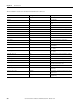
SR07_ProcessAlarms Sets the alarm status bit for the following alarms:
• Power monitor communication loss
• Invalid Power monitor Demand Configuration
• Insufficient Sheddable Load
• [Load Name] Load Shed Failed alarm
• Only 1 Sheddable Load Available