
t Owner manual

380 Rockwell Automation Publication IASIMP-QS016C-EN-P - October 2014
Chapter 12 Demand Control
System Application Guide
This section guides you through the pre-configured FactoryTalk View Machine Edition faceplate providing you with an
understanding of the status, control, and diagnostic operation of the faceplate display.
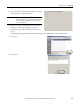
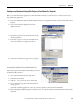
Faceplate Operation Overview
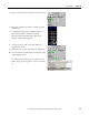
The Demand Control Faceplate opens with the Demand Control Status displayed.
Title Bar
Faceplate Toolbar
Load Status
Indicators
Close Button
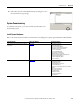
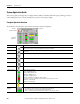
Button Icons Description
Alarm The alarm button indicates an alarm condition and activates alarm diagnostic views. A grey bell indicates normal
status, with no alarms. A red flashing bell indicates an alarm condition.
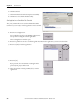
Configuration The Configuration button displays the main demand control configuration screen (upon entering the correct
password).
Load 1…8 The Load 1-8 button lets you view the load status and descriptive name for loads 1…8
Load 9…16 The Load 9-16 button lets you view the load status and descriptive name for loads 9…16
Help The Help button provides information for the existing view.
Close Click the Close button to close the faceplate.
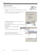
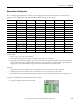
Status Indicators Grey = Off/Normal Control
Green = On/Normal Control
D-Grey = Off/Demand Control
OVR-Grey = Off/Override Set
OVR-Green = On/Override Set
OVR-Red = On/Override Set/Operator Action Required
Red Flashing = Load is not in OVR, controller telling to turn off, but load is still on.
INT-Green = Interlocked On
INT-Grey = Interlocked Off
Interlocks Bypassed Indicates that the interlocks have been bypassed for the load.
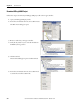
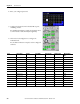
Predicted KW
Demand
The predicted KW demand is read from the PowerMonitor with the following color code
• Red = Operator Action Required to stay within Demand kW Setpoint
• Yellow = Shedding Loads to stay within Demand kW Setpoint
• Green = Predicted Demand within Demand kW Setpoint - Shedding not required