
t Owner manual

360 Rockwell Automation Publication IASIMP-QS016C-EN-P - October 2014
Chapter 12 Demand Control
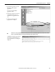
Follow These Steps
The following steps are based on a CompactLogix 1769-L23E-QBFC1 packaged controller, but the general steps may be
applied to other Logix controller configurations and are similar. Follow these steps to implement your Demand Control
application.
• Control Hardware Selection and Wiring
• Logic Integration
• HMI Integration
• System Commissioning
Control Hardware Selection and Wiring
Follow these steps to determine the hardware required for your application.
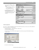
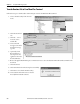
List Load Outputs and Inputs
1. Determine which loads in your application will be controlled by the Demand controller (maximum of 16 loads).
2. Number each load from 1…16.
3. List the outputs and inputs associated with each load.
As a minimum each load must accept a command to stop from the Demand Controller. The Demand Controller
also accepts a load status input that is used for indication and alarming, however this is not required.
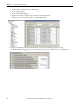
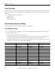
In the Efficient Industries Plant 1 example, the monitoring and analysis revealed some significant energy savings if
Demand control was used to control the loads identified below.
Load Description Output I/O Location Input I/O Location
1 Air Compressor 1 Local:2:O.Data.0 Local:1:I.Data.0
2 Air Compressor 2 Local:2:O.Data.1 Local:1:I.Data.1
3 AHU 1 Production Local:2:O.Data.2 Local:1:I.Data.2
4 AHU 2 Production Local:2:O.Data.3 Local:1:I.Data.3
5 AHU 3 Shipping Local:2:O.Data.4 Local:1:I.Data.4
6 AHU 4 Office Local:2:O.Data.5 Local:1:I.Data.5
7 Exhaust Fan 1 Local:2:O.Data.6 N/A
8 Exhaust Fan 2 Local:2:O.Data.7 N/A
9 Exhaust Fan 3 Local:2:O.Data.8 N/A
10 Exhaust Fan 4 Local:2:O.Data.9 N/A
11 Lighting Production Local:2:O.Data.10 Local:1:I.Data.6
12 Lighting Production Local:2:O.Data.11 Local:1:I.Data.7
13 Lighting Shipping Local:2:O.Data.12 Local:1:I.Data.8
14 Lighting Office Local:2:O.Data.13 Local:1:I.Data.9