
t Owner manual

322 Rockwell Automation Publication IASIMP-QS016C-EN-P - October 2014
Chapter 11 FactoryTalk View ME Energy Faceplates
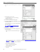
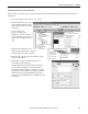
8. Click OK to accept the default setup for the new message
tag.
9. Click the Browse icon next to the
xxx_MsgTotalRealPower tag to open the Message
Configuration dialog box.
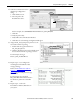
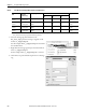
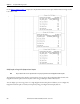
10. Choose PLC5 Typed Read for Message Type.
11. Enter the associated PM1000 or PM3000 PLC5 address
as the Source Element.
For this example, F17:3 is entered for the PM 3000 Real
Power PLC5 address.
Refer to PowerMonitor Add-On Instruction Tag
References table on page 321 for the PLC5 address.
12. Set the Number of Elements to 1.
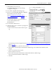
13. Click New Tag to create a controller-scoped tag for the
Destination Element.
a. Enter a name for the associated controller-scoped
tag.
Use the Message Destination Tag, xxx_TotalRealPower, defined in the PowerMonitor Add-On Instruction Tag
References table on page 321.
For this example, enter Electric_Main_TotalRealPower.
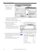
b. Choose REAL as the Data Type.
c. Choose a controller from the Scope list.
For this example, L2x is selected.
d. Choose Float for Style.
e. Click OK.