Quick Start Energy Management Accelerator Toolkit Energy Assessment and Monitoring Methods System Configuration and Wiring Energy Data Collector Configuration FactoryTalk EnergyMetrix Configuration and Maintenance Local HMI Integration
Important User Information Read this document and the documents listed in the additional resources section about installation, configuration, and operation of this equipment before you install, configure, operate, or maintain this product. Users are required to familiarize themselves with installation and wiring instructions in addition to requirements of all applicable codes, laws, and standards.
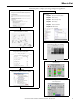
Where to Start Follow this path to complete your energy management application.
Where to Start Notes: 4 Rockwell Automation Publication IASIMP-QS016C-EN-P - October 2014
Table of Contents Preface About This Publication. . . . . . . . . . . . . . . . . . . . . . . . . . . . . . . . . . . . . . . . . . . Conventions. . . . . . . . . . . . . . . . . . . . . . . . . . . . . . . . . . . . . . . . . . . . . . . . . . . . . Software Requirements . . . . . . . . . . . . . . . . . . . . . . . . . . . . . . . . . . . . . . . . . . . Studio 5000 Environment. . . . . . . . . . . . . . . . . . . . . . . . . . . . . . . . . . . . . Additional Resources . . . . . . . . . . . . . . . . . .
Table of Contents Configure a PowerMonitor 5000 Device . . . . . . . . . . . . . . . . . . . . . . . . . . . Setup Using the Web Interface. . . . . . . . . . . . . . . . . . . . . . . . . . . . . . . . . Obtaining Access to the Configuration Pages . . . . . . . . . . . . . . . . . . . How to Set Up the PowerMonitor 5000 Unit. . . . . . . . . . . . . . . . . . . Configure a CompactLogix Controller . . . . . . . . . . . . . . . . . . . . . . . . . . . . .
Table of Contents Configure a CompactLogix Device . . . . . . . . . . . . . . . . . . . . . . . . . . . . . . . 130 Configure OPC Server Device . . . . . . . . . . . . . . . . . . . . . . . . . . . . . . . . . . . 132 Chapter 7 FactoryTalk EnergyMetrix Software Meter and Tag Setup Introduction. . . . . . . . . . . . . . . . . . . . . . . . . . . . . . . . . . . . . . . . . . . . . . . . . . . . Before You Begin. . . . . . . . . . . . . . . . . . . . . . . . . . . . . . . . . . . . . . . . . . . . . . . .
Table of Contents Set Up Database Maintenance . . . . . . . . . . . . . . . . . . . . . . . . . . . . . . . . . . . . Automatic Data Repopulation. . . . . . . . . . . . . . . . . . . . . . . . . . . . . . . . . . . . Devices that Support ADR . . . . . . . . . . . . . . . . . . . . . . . . . . . . . . . . . . . Monitor Health of Data Logging . . . . . . . . . . . . . . . . . . . . . . . . . . . . . . . . . Using the Windows Event Viewer . . . . . . . . . . . . . . . . . . . . . . . . . . . . . . . .
Table of Contents CIP Motion Energy Faceplate Overview. . . . . . . . . . . . . . . . . . . . . . . Configure Device Logic for Equipment Status and Alarm History Faceplates. . . . . . . . . . . . . . . . . . . . . . . . . . . . . . . . . . . . . . . . . . . . . . . Configure Equipment Status Faceplate. . . . . . . . . . . . . . . . . . . . . . . . . . . . Configure Alarm History Faceplate. . . . . . . . . . . . . . . . . . . . . . . . . . . . . . . Create a Runtime Application File. . . . . . . . . . . . .
Table of Contents List Load Outputs and Inputs. . . . . . . . . . . . . . . . . . . . . . . . . . . . . . . . . Create Control Panel Layout and Wiring . . . . . . . . . . . . . . . . . . . . . . Logic Integration . . . . . . . . . . . . . . . . . . . . . . . . . . . . . . . . . . . . . . . . . . . . . . . . Configure Controller, Network, and I/O . . . . . . . . . . . . . . . . . . . . . . Import and Configure Time of Day Program. . . . . . . . . . . . . . . . . . . Configure Load Inputs and Outputs . . . .
Table of Contents Alarm History Faceplate Logic . . . . . . . . . . . . . . . . . . . . . . . . . . . . . . . . . . . 444 Appendix E Update Add-on Profiles Update the E3PLUS Add-On Profiles . . . . . . . . . . . . . . . . . . . . . . . . . . . . Update the SMC-50 Add-On Profiles . . . . . . . . . . . . . . . . . . . . . . . . . . . . Update the PowerFlex Add-On Profiles . . . . . . . . . . . . . . . . . . . . . . . . . . . Update the E300 Add-On Profiles. . . . . . . . . . . . . . . . . . . . . . . . . .
Table of Contents Notes: 12 Rockwell Automation Publication IASIMP-QS016C-EN-P - October 2014
Preface About This Publication This quick start is designed to provide a framework for developing an energy management monitoring, analysis, and control application for your facility. Each section guides you through the tasks you need to plan, configure, program, and use your Rockwell Automation energy data collection and control devices and analysis software. An example application, named Efficient Industries Plant 1, is referenced throughout this quick start to guide you through these tasks.
Preface Conventions The manual uses the following conventions. Convention Meaning Example Click Click the left mouse button once to initiate an action. (Assumes cursor is positioned on object or selection.) Click Browse. Double-click To initiate an action, click the left mouse button twice in quick succession while the cursor is positioned on object or selection. Double-click the application icon.
Preface Studio 5000 Environment The Studio 5000 Engineering and Design Environment combines engineering and design elements into a common environment. The first element in the Studio 5000 environment is the Logix Designer application. The Logix Designer application is the rebranding of RSLogix 5000 software and continues to be the product to program Logix5000™ controllers for discrete, process, batch, motion, safety, and drive-based solutions.
Preface Additional Resources These documents contain additional information concerning related products from Rockwell Automation. Resource Description PowerMonitor 1000 Unit Installation Instructions, publication 1408-IN001 Provides information on installing, wiring, connecting, applying power and configuring the PowerMonitor 1000 unit.
Chapter 1 Energy Assessment and Monitoring Methods Introduction This chapter introduces the fundamentals of creating an energy management plan that will help you to: • determine your business goals. • perform a plant walk-through. • perform an energy assessment. • understand the business case for energy monitoring. • review the monitoring methods available when applying Rockwell Automation energy management hardware and software products.
Chapter 1 Energy Assessment and Monitoring Methods Determine Business Goals Business today has changed and it added a color - green. Not only do you need to meet your business and production goals, but global dynamics are forcing you to pursue energy reductions. Many companies can help reduce energy consumption at their manufacturing facilities when a plan is implemented.
Energy Assessment and Monitoring Methods Chapter 1 Energy Assessment The assessment process is a detailed analysis of the data collected during the walk-through. Identifying opportunities for energy savings and developing the return on investment for these projects is critical. Energy assessments should identify not only opportunities, but savings, project costs, and payback calculations. Projects should also be categorized as awareness or behavior changes, minor cost, and capital.
Chapter 1 Energy Assessment and Monitoring Methods Sample Rate Schedules 20 Rockwell Automation Publication IASIMP-QS016C-EN-P - October 2014
Energy Assessment and Monitoring Methods Chapter 1 Sample Energy Assessment Here is an example of a compressed air plant system assessment.
Chapter 1 Energy Assessment and Monitoring Methods How Rockwell Can Help Rockwell Automation has a team of engineers that are experienced in conducting energy assessments for energy sources including, but not limited to, electricity, gas, water, air, and steam. To help you identify energy cost savings opportunities, Rockwell Automation can perform a general energy assessment that will help you create a sustainable plan.
Energy Assessment and Monitoring Methods Chapter 1 Business Case for Energy Monitoring Energy monitoring makes energy usage data visible so that it is included in the planning and execution of a business strategy along with other management information. Because utility bills can be a significant portion of business expense, it is important to understand how energy is used. Implementing a monitoring plan will help your business set goals for energy reduction that will translate into cost savings.
Chapter 1 Energy Assessment and Monitoring Methods Monitoring Methods Rockwell Automation power monitors and controllers collect data from your plant floor that can be used by FactoryTalk EnergyMetrix software for monitoring and analysis. FactoryTalk EnergyMetrix software provides monitoring and reporting tools to help you understand usage patterns, optimize processes, and reduce utility costs in your organization.
Energy Assessment and Monitoring Methods Chapter 1 Consumption Reporting Consumption reporting typically monitors periodic utility usage, production, or other key performance indicators, and assists with the early detection of production/equipment problems such as leaks, inefficiencies, and production problems. Demand Analysis Demand analysis monitors the electrical demand of plant areas so that you can make energy saving production scheduling or demand control decisions.
Chapter 1 Energy Assessment and Monitoring Methods Shadow Billing Shadow billing generates a replication of a monthly bill from your energy provider for comparative billing analysis and potential energy cost recovery. Cost Allocation Cost allocation monitoring lets you allocate energy costs based on actual usage that is based on production area submetering rather than other measurements such as square footage allocation. Effective cost allocation helps drive energy accountabilities to the user.
Energy Assessment and Monitoring Methods Chapter 1 Power Quality Power quality monitoring lets you capture power quality events or conditions that could cause a production shutdown like voltage sags, swells, and brownouts.
Chapter 1 Energy Assessment and Monitoring Methods Notes: 28 Rockwell Automation Publication IASIMP-QS016C-EN-P - October 2014
Chapter 2 System Configuration and Wiring Introduction In this chapter, you will do the following: • • • • • List energy data points based on your business goals and energy monitoring plan. Identify your existing energy meters and distribution systems. Select data collection hardware and create a meter layout. Create panel layouts and wiring for your data collection hardware. Select required software.
Chapter 2 System Configuration and Wiring Follow These Steps Follow this path to layout your energy panel and wiring, and select monitoring software.
System Configuration and Wiring Chapter 2 List Energy Data Points You will now review your business goals and energy monitoring plan, then enter your data points in the Energy Data Worksheet. Review Business Goals and Energy Monitoring Plan 1. Review the business goals that you created in Chapter 1. The Efficient Industries Plant 1 example, referenced throughout this quick start, is a midsized plant with two production areas.
Chapter 2 System Configuration and Wiring 2. Right-click Energy Data Worksheet and open the file. When opening the spreadsheet, select Enable Macros. 3. Click the Energy Point tab in the worksheet and enter an energy type and name for the first energy data point in your system. a. Select a cell in the Energy Type column and click the pull-down list icon. b. Choose an Energy Type. For the Efficient Energy Plant 1 example, choose Electricity. c.
System Configuration and Wiring Chapter 2 Identify Existing Energy Distribution Layouts and Metering Follow these steps to help identify your existing energy distribution and metering systems. 1. Gather existing electrical distribution single line drawings and label electricity data point substations and distribution points.
Chapter 2 System Configuration and Wiring 2. Gather or create the electrical distribution plant layout.
System Configuration and Wiring Chapter 2 3. Gather or create other energy distribution plant layouts.
Chapter 2 System Configuration and Wiring Create Metering Layout and Name Data Collection Hardware In this section, you will create a metering layout, then select and name your data collection hardware using the Energy Data Worksheet. The information entered in the worksheet will be used later in the FactoryTalk EnergyMetrix software configuration chapters.
System Configuration and Wiring Chapter 2 2. Browse to the System Layout and Wiring folder on your Energy Management Accelerator Toolkit CD image and open the Energy Data Worksheet. 3. Click the FactoryTalk EnergyMetrix tab and select a Device Class for each PowerMonitor added to the layout. The device classes will be used in later chapters when configuring devices in FactoryTalk EnergyMetrix software and also determine the energy meter tag names. a.
Chapter 2 System Configuration and Wiring For the Efficient Industries Plant 1 example, the electricity energy data point listing would look like this. 4. Identify other digital energy data points in close proximity that you can connect to the status inputs of the PowerMonitors. For the Efficient Industries Plant 1 example, the air flow digital pulse meter is near the Production 2 electrical substation so it can connect to the PowerMonitor 1000 named Production 2. 5.
System Configuration and Wiring Chapter 2 6. Identify other small groups (<3) of digital energy points in close proximity that can be collected by the digital status inputs of the PowerMonitor 1000 device. This is a lower cost alternative to a CompactLogix™ controller with a few digital inputs. For the Efficient Industries Plant 1 example, the gas main and water main digital meters are somewhat isolated in the corner of the production area near MCC 2.
Chapter 2 System Configuration and Wiring The L23 CompactLogix controller can collect up to 16 digital inputs and 4 analog inputs. For the Efficient Industries Plant 1 example, the remaining digital and analog energy data points are in the Boiler House so a CompactLogix controller is added to the metering layout. 9. Select a Device Class and Meter Type on the FactoryTalk EnergyMetrix tab of the Energy Data Worksheet for the digital and analog energy inputs identified in step 8. a.
System Configuration and Wiring Chapter 2 11. Select a Device Class and Meter Type on the FactoryTalk EnergyMetrix tab of the Energy Data Worksheet for the OPC server data point identified in step 10. a. Select OPC Server on Ethernet for the Device Class. b. Select OPC for the Meter Type. For the Efficient Industries Plant 1 example, the entry for the OPC server data point would look like this.
Chapter 2 System Configuration and Wiring Select Data Collection Hardware Follow these steps to select your data collection hardware. 1. Browse to the System Layout and Wiring folder on the Energy Management Accelerator Toolkit CD image and open the Energy Data Worksheet. 2. Click the FactoryTalk EnergyMetrix tab then choose or enter energy device catalog numbers. a. Select a cell in the Cat. No. column and click the pull-down list icon. b. Choose the appropriate Cat. No.
System Configuration and Wiring Device (1) PowerMonitor 500 PowerMonitor 5000 CompactLogix L23 Controllers Chapter 2 Cat. No.
Chapter 2 System Configuration and Wiring Name Data Collection Hardware Follow these steps to create or select device names, meter types, and meter tag names for each energy data point. These names will be used later in the FactoryTalk EnergyMetrix software configuration chapters. 1. Click the FactoryTalk EnergyMetrix tab on the Energy Data Worksheet. 2. Enter a device name for each energy data point.
System Configuration and Wiring Chapter 2 3. Review meter names. The meter names are autopopulated in the worksheet based on energy data point names. 4. Choose Electric as the Meter Type for all the PowerMonitor devices. 5. Select or enter meter tag names for each data point based on the Energy Type and Meter Type shown in the table.
Chapter 2 System Configuration and Wiring For the Efficient Industries Plant 1 example, the meter type and meter tag name listing would look like this. Assign CompactLogix Input Addresses Follow these steps to assign CompactLogix hardware input addresses and corresponding PLC-5 mapped tags to the energy data points. 1. Click the CompactLogix tab on the Energy Data Worksheet. 2. Enter an L2x address for each energy data point that is connected to a CompactLogix controller. a.
System Configuration and Wiring Chapter 2 3. Select the corresponding PLC-5 mapped address for the energy data point. a. Select a cell in the PLC-5 Address column and click the pull-down list icon. b. Choose a PLC-5 File 10 address to which the energy data point will be mapped for communicating with FactoryTalk EnergyMetrix software. TIP It is recommended that you assign consecutive PLC-5 addresses in a single file to simplify mapping. Refer to page 86 for details on mapped PLC-5 addresses.
Chapter 2 System Configuration and Wiring Create Energy Panel Layout and Wiring Drawings The toolkit provides energy data collector panel layout and wiring drawings in DWG, DXF, and PDF file formats to help you plan the layout of your energy system. The files are organized by device (CompactLogix, PM1000, PM3000, PMW250, PM500, and PM5000). The drawings include power and control wiring. If you do not have CAD software, use the pdf files to build your system drawings.
System Configuration and Wiring Chapter 2 Panel Layout Drawings The AutoCAD Electrical project includes several panel-layout drawings for the PowerMonitor 1000, PowerMonitor 3000, and CompactLogix data collector devices. Choose an appropriate drawing as a starting point. Add or remove components as needed. This example shows an energy panel layout with a PowerMonitor 3000 device.
Chapter 2 System Configuration and Wiring Wiring Drawings The AutoCAD electrical project includes a variety of electrical power wiring configurations for PowerMonitor 1000 and PowerMonitor 3000 devices plus power and control wiring drawings for the CompactLogix L23E controller. This drawing shows PowerMonitor 3000 device wiring for a 480V, 4-wire WYE direct system.
System Configuration and Wiring Chapter 2 Access Other Allen-Bradley CAD Drawings Follow these steps to download other Allen-Bradley® product CAD drawings. 1. Open your browser and go to http://ab.com/e-tools. The Configuration and Selection Tools webpage opens. TIP If you know the complete catalog number of your Allen-Bradley product, you can enter it here and click Submit. However, you need a complete catalog number string to get the configuration results. 2.
Chapter 2 System Configuration and Wiring Select Monitoring Software Use these tables to select the FactoryTalk EnergyMetrix software appropriate for your application requirements. Every FactoryTalk EnergyMetrix system must include a Manager license of 8, 64, or 1000 meters. License Options FactoryTalk EnergyMetrix software is a scalable, modular software application. Its components and capabilities are determined by the licenses purchased and installed by the user.
System Configuration and Wiring Chapter 2 Server Requirements We recommend, but do not require, that you install FactoryTalk EnergyMetrix software on a dedicated server with a local installation of Microsoft SQL Server. Server Software Requirements for Installing FactoryTalk EnergyMetrix Software • Windows 2003 Server or Windows 2008 Server, Application Server role. For 64-bit operating systems, RSLinx Classic software version 2.57 CPR9 SR3 or later must be installed.
Chapter 2 System Configuration and Wiring Recommendations These are general guidelines. FactoryTalk EnergyMetrix software is capable of running on a variety of hardware platforms. The main scalability issue is related to processing of logged data (for example, report generation, trending). CPU speed, number of CPUs, RAM, and RAID 5 for the database files are the main scalability factors (in that order).
Chapter 3 Energy Data Collector Configuration Introduction In this chapter, you configure data collector devices for your energy management application. This can include PowerMonitor W250, 500, 1000, 3000, or 5000 devices and CompactLogix controllers. PowerMonitor devices typically gather electrical energy data through connections to electrical distribution systems. In addition, PowerMonitor devices can connect to digital pulse outputs from gas, water, and other types of energy meters.
Chapter 3 Energy Data Collector Configuration Follow These Steps Follow these paths to configure the PowerMonitor devices and Compactlogix controllers in your energy system.
Energy Data Collector Configuration Chapter 3 Configure a PowerMonitor 3000 Device This section shows you how to configure PowerMonitor 3000 device settings by using the PowerMonitor 3000 display module. Certain settings are needed for the power monitor to meter accurately, communicate correctly, and work with FactoryTalk EnergyMetrix software properly. These settings include network configuration, wiring, PT and CT ratios, nominal system voltage, demand settings, and the date/time.
Chapter 3 Energy Data Collector Configuration Configure the Ethernet IP Address Follow these steps to configure the Ethernet IP address of the PowerMonitor 3000 module. The default IP address is 192.168.254.xxx, where xxx is the unit’s id. Before starting the procedure, make sure the PowerMonitor 3000 display module is connected to the PowerMonitor 3000 device and control power is on. TIP 1. Press the Down Arrow key to select PROG mode. 2. Press the Enter key to access Edit mode. You should see PASS.
Energy Data Collector Configuration Chapter 3 Configure Basic Device Parameters Follow these steps to configure wiring, PT and CT ratios, and nominal system voltage for the PowerMonitor 3000 device. The Basic Device Configuration Parameters table on page 59 provides a list of basic device configuration parameters and example settings. 1. Press the Enter key from the PROG.>CONFIGURATION menu. The BASIC configuration menu is displayed. 2. Press the Enter key to select the WIRING CONFIG. menu. 3.
Chapter 3 Energy Data Collector Configuration Configure Advanced Device Parameters The Advanced Device Configuration Parameters table on page 61 provides a list of advanced parameters and values you can set for the PowerMonitor 3000 device. Most applications use the default values for demand period length, number of demand periods, and forced demand delay. Follow these basic steps to configure demand parameters and the date/time. 1. Press the Enter key from the PROG.>CONFIGURATION menu.
Energy Data Collector Configuration Chapter 3 Advanced Device Configuration Parameters Parameter Range Default Example Settings New Password -1…9999 0000 0000 Demand Period Length -99…99 min 15 15 Number of Demand Periods 1…15 1 1 Forced Demand Delay 0…900 s 10 10 Predicted Demand Type Instantaneous 1st Order 2nd Order Instantaneous KYZ Control Source 0 = None 1 = Wh Forward 2 = Wh Reverse 3 = VARh Forward 4 = VARh Reverse KYZ Pulse Output Scale 1…30000 10 5 = Vah 6 = Ah 7 = Se
Chapter 3 Energy Data Collector Configuration Configure a PowerMonitor 1000 Device This section shows you how to configure parameters of a PowerMonitor 1000 device by using its internal Display and Configuration web page. Certain settings are needed for the PowerMonitor to meter accurately, communicate correctly, and work with FactoryTalk EnergyMetrix software properly. You will set the network configuration, voltage mode, PT and CT ratios, demand values, and the date and time.
Chapter 3 Energy Data Collector Configuration 2. Enter the default password of 0 or another valid password to access Edit mode. TIP The password appears as asterisks (*). If you don’t know the password, call Rockwell Automation technical support for assistance. 3. Enter appropriate values in the IP Address Byte fields. For the Efficient Industries Plant 1 example, the IP address is 10.10.10.1 for the first PowerMonitor 1000 device. 1 4. Enter the Subnet Mask and Gateway IP addresses as required. 5.
Chapter 3 Energy Data Collector Configuration 2. Enter the default password of 0 or another valid password to access Edit mode. TIP The password appears as asterisks (*). If you don’t know the password, call Rockwell Automation technical support for assistance. 3. Enter the value of the Voltage Mode you are using. 4. Set elements 2, 3, and 4 to configure the PT and CT parameters. 5. Click Submit to send the parameter changes to the PowerMonitor 1000 device.
Energy Data Collector Configuration Chapter 3 Configure Advanced Device Parameters Follow these steps to configure advanced demand parameters for the PowerMonitor 1000 device. These settings include demand source, demand period length, and the number of demand periods to average for the demand calculation. The Advanced Device Configuration Parameters table on page 65 shows the demand parameters and example settings. 1. Choose Configure Options>Advanced to access the Advanced Configuration page. 2.
Chapter 3 Energy Data Collector Configuration Configure the Date and Time Follow these steps to configure the date and time for the PowerMonitor 1000 device. The Date and Time Setup Parameters table on page 66 shows the date and time parameters, and example settings 1. Choose Configure Options>Date and Time to access the Date and Time Configuration page. 2. Enter the default password of 0 or another valid password to access Edit mode. TIP The password appears as asterisks (*).
Energy Data Collector Configuration Chapter 3 Configure a PowerMonitor Wireless 250 Device The PowerMonitor Wireless 250 monitors are factory configured. Each PowerMonitor Wireless 250 device is assigned a Group ID and Device ID in the factory. These should not be modified except under exceptional circumstances. One such circumstance would be operating two or more independent PowerMonitor W250 networks in such close proximity that RF interference with each other occurs.
Chapter 3 Energy Data Collector Configuration As soon as power is applied to the PC Receiver unit, the PC Receiver unit chooses the serial mode, RS-232 or RS-485, according to the DB9 wiring. This mode remains until the PC Receiver is power cycled (just removing the DB9 connector does not change the serial mode). RS-485 mode is available on the PC Receiver unit with the date code 10267 or later with firmware revision (or later) 1.5.15 (100 and 200 node) or 1.7.5.15 (10 node).
Energy Data Collector Configuration Chapter 3 When the cursor is beneath the last digit on the left, a further press of Escape (6) lets you change the decimal point and the multiplier (9) (k or M). The blinking ‘dP’ (decimal point) text (10) indicates this capability. To modify the decimal point position and the multiplier, use the Up and Down arrow button (7) to select the desired value. 9 10 To store the new programmed value, press Enter (7).
Chapter 3 Energy Data Collector Configuration The Ethernet communication parameters are listed in this table. Parameter Range Default IP Address www.xxx.yyy.zzz N/A Subnet www.xxx.yyy.zzz N/A Gateway www.xxx.yyy.zzz N/A TCP IP Port 1…9999 502 ACD Yes or No No 4. To change a parameter: a. Press Enter to select a menu item. b. Press the Up and Down arrows to change the value. c. When the desired value is displayed, press Enter to confirm your selection. 5.
Energy Data Collector Configuration Chapter 3 These are the Demand configuration parameters. Parameter(1) Range Default Type FIXED AVG/DMD SLIDE FIXED Time 01, 05, 10, 15, 20, 30 15 Sync OFF/CLOCK OFF (1) Additional advanced parameters, such as alarms, outputs, and digital filtering are also available for configuration. Refer to the PowerMonitor 500 Unit User Manual, publication 1420-UM001, for detailed information. 3. To change a parameter: a. Press Enter to select a menu item. b.
Chapter 3 Energy Data Collector Configuration Configure a PowerMonitor 5000 Device This section shows you how to configure parameters of a PowerMonitor 5000 device by using the Web interface. Certain settings are needed for the power monitor to meter accurately, communicate correctly, and work with FactoryTalk EnergyMetrix software properly. You will set the basic metering, native Ethernet communication, date and time, and initial security configuration.
Energy Data Collector Configuration Chapter 3 If Security is Enabled If security is enabled, the web page header displays ‘Logged in as:’ and a Log in link. If security is enabled, you will need to log in as an administrator to configure setup parameters. If not logged in as an administrator, you will be able to view, but not change, configuration parameters. If you need to log in, click the Log in link. The USB connection has a special administrator account.
Chapter 3 Energy Data Collector Configuration Basic Metering Setup We will begin with configuring the basic metering parameters. Click the Metering_Basic page under the open Configuration folder. The page opens. You can select other configuration pages by clicking the desired page in the tree, or by clicking the corresponding tab in the page.
Energy Data Collector Configuration EXAMPLE Chapter 3 This example explains how to change from a DHCP-assigned to a static IP address. The initial network configuration is shown below. The IP address assigned is 192.168.200.8. The network administrator has provided a range of static IP addresses in the same subnet, beginning with 192.168.200.100.
Chapter 3 Energy Data Collector Configuration Set Up Date and Time Click the Configuration folder and select the DateTime page. Enter the year, month, day, hour, and minute into the corresponding input fields and click Apply Changes. If your power monitor has been set up for time synchronization with either a SNTP or IEEE 1588 PTP server, the time may already be set.
Energy Data Collector Configuration Chapter 3 Only one admin type account is permitted to be active at a time. Now that the network administrator user has been created, you can continue setting up the PowerMonitor 5000 unit by connecting through the native EtherNet/IP port and using the network Web interface. This includes the ability to configure additional users, administrators, and application security accounts. Test Security To test the network administrator login, follow these steps. 1.
Chapter 3 Energy Data Collector Configuration Configure a CompactLogix Controller In this section, you set up a CompactLogix controller as a FactoryTalk EnergyMetrix data collector, and interface to local HMI faceplates. You configure controller properties, digital and analog energy inputs, and energy Add-On Instructions for each controller in your system. Refer to the CompactLogix tab in the Energy Data Worksheet created in Chapter 2 for CompactLogix and PLC-5 address assignments.
Energy Data Collector Configuration Chapter 3 Import Energy Add-On Instructions You will now import preconfigured Energy Add-On Instructions to support the digital and analog energy inputs listed on the CompactLogix tab of your Energy Data Worksheet. These Add-On Instructions provide energy data calculations and HMI interface logic for the energy inputs. Refer to Appendix C and Appendix D for detailed logic information. 1. Navigate to and right-click the AddOn Instructions folder. 2.
Chapter 3 Energy Data Collector Configuration 6. Click OK from the Import Configuration dialog box to continue the Add-On Instruction import. 7. Verify the imported file appears under Add-On Instructions. 8. Repeat steps 1…7 to import other required Add-On Instruction files for your project. For the Efficient Industries Plant 1 example, the AddOn Instructions list would look similar to this.
Energy Data Collector Configuration Chapter 3 2. Click the Add-On tab in the instruction toolbar. 3. Click an Energy Add-On Instruction icon to add the instruction to your rung. For this example, the Energy_Gas_Digital Add-On Instruction is selected. 4. Click in the energy tag name field and enter a tag name. For this example, Boiler_House_Gas is entered. 5. Right-click the energy tag name just entered and choose the New “Tag_Name” from the list. 6.
Chapter 3 Energy Data Collector Configuration 7. Double-click the input parameter field, then click the pull-down menu icon to display the input controller tags. Refer to the CompactLogix tab of the Energy Data Worksheet for the local I/O digital or analog input address. 8. Navigate to the desired digital or analog input tag. This example shows Local:1:I.Data. 9. For digital input tags: a. Click the tag pull-down menu icon to display a table of data bits. b.
Energy Data Collector Configuration Chapter 3 10. Assign energy input calculation and scaling factor tag values based on the Energy Add-On Instruction Factor table definitions on page 84. One table provides factor definitions for electric inputs and one for all other energy inputs. This example shows values that need to be set for the Energy_Gas_Digital Add-On Instruction.
Chapter 3 Energy Data Collector Configuration Energy Add-On Instruction Factors for Electric Inputs Energy Factor Tag Description Set_Meter_Pulse_Factor The kWh value used to scale the input pulses. The value 1.5 represents 1.5 kWh per pulse. Set_Demand_Interval The value, in minutes, used to calculate the End of Demand Interval (EOI). This value is used only if the Val_End_of Demand_Type is 2.
Energy Data Collector Configuration Chapter 3 11. Repeat steps 1…10 to program other digital and analog energy inputs in your project. For the Efficient Industries Plant 1 example, the completed energy input logic would look similar to this.
Chapter 3 Energy Data Collector Configuration Map Energy Add-On Instruction Tags to PLC-5 Addresses After programming the CompactLogix energy Add-On Instructions, you must map the total energy tags (AOIName.Val_Total_xxx) to PLC-5 type addresses (Fxx:x) that FactoryTalk EnergyMetrix software can read. You will create a MOV instruction for each Compactlogix energy Add-On Instruction to move its total to a tag within an array named ControllerName_EnergyTotals.
Energy Data Collector Configuration Chapter 3 2. Add the MOV instruction to your rung by clicking the Move/ Logical tab in the Instruction toolbar, then clicking the MOV instruction icon. 3. Choose the source tag, Val_Total_xxx, from your energy Add-On Instruction. For this example, Boiler_House_Gas.Val_Total_Gas is selected. 4. Enter a name for the new controller-scoped destination tag in the format: ControllerName_EnergyTotals. For this example, enter L2x_EnergyTotals. 5.
Chapter 3 Energy Data Collector Configuration 7. Double-click the Dest tag assignment in the MOV instruction and reassign the Dest tag to a unique ControllerName_EnergyTotals array element in the CompactLogix tab of the Energy Data worksheet. This example shows the instruction used to move Boiler_House_Gas.Val_Total_Gas to the L2x_EnergyTotals file element [0]. 8. Repeat steps 2, 3, and 7 to program MOV instructions for the remaining Add-On Instruction total energy tags (AOIName.Val_Total_xxx.) 9.
Energy Data Collector Configuration Chapter 3 For the Efficient Industries Plant 1 example, the completed energy Add-On Instruction tag-mapping logic would look similar to this.
Chapter 3 Energy Data Collector Configuration Notes: 90 Rockwell Automation Publication IASIMP-QS016C-EN-P - October 2014
Chapter 4 FactoryTalk EnergyMetrix Software Installation Introduction In this chapter, you will install server software and FactoryTalk EnergyMetrix software on your computer, and launch FactoryTalk EnergyMetrix software from your web browser. Before You Begin • Determine business goals, complete energy assessment, and determine monitoring methods (Chapter 1). • Select hardware and wire devices (Chapter 2). • Configure data collection devices (Chapter 3).
Chapter 4 FactoryTalk EnergyMetrix Software Installation Follow These Steps Follow these steps to install server software, prerequisite software, and FactoryTalk EnergyMetrix software on your computer. You will also modify settings to use FactoryTalk EnergyMetrix RT and Chart options and launch FactoryTalk EnergyMetrix software. Enable 32-bit Applications Server Requirements page 98 page 93 Install FactoryTalk EnergyMetrix Software Version 2.
FactoryTalk EnergyMetrix Software Installation Chapter 4 Contents of Installation DVD The installation DVD contains the following required components: • FactoryTalk EnergyMetrix software version 2.00.00 • FactoryTalk Activation Manager version 3.50 • RSLinx Classic Lite 2.57 CPR 9 SR 3 • Microsoft .NET Framework 3.5 SP1 And the following optional components: • Adobe Acrobat Reader 9.
Chapter 4 FactoryTalk EnergyMetrix Software Installation Database Size Guidelines FactoryTalk EnergyMetrix writes 16 bytes of data to the database for each meter tag logged. Over time, the database can grow to become quite large. Some examples include the following: • A low-end server, logging 40 meter tags at 15 minute intervals, will grow the database at a rate of 2.56 KB per hour or 22 MB per year.
FactoryTalk EnergyMetrix Software Installation Chapter 4 • Adobe Acrobat Reader 7.0 software or later is required to view reports. • Microsoft .NET Framework 3.5 SP1 is required to use RT and Charts Plus options. .NET Framework 3.5 SP1 is included on the installation DVD or can be downloaded at no charge from Microsoft. Your client workstation must also be permitted Intranet, Internet or dial-in access to the FactoryTalk EnergyMetrix server. Contact your IT support personnel for assistance.
Chapter 4 FactoryTalk EnergyMetrix Software Installation 10. Click Next. 11. Click Next. 12. Scroll down in the Role Services window and then select IIS 6 Management Compatibility. 13. Click Next. 14. Click Install. 15. Wait while installation proceeds. 16. Click Close when done. TIP We recommend that you disable Internet Explorer Enhanced Security Configuration. 17. To do this, locate the Configure IE ESC link in the Security section In the Server Manager. 18.
FactoryTalk EnergyMetrix Software Installation Chapter 4 14. Select the features shown as selected in the screen capture. 15. Click Next. 16. Click Next. 17. Leave the Default instance selected, click Next. 18. On the Disk Space Requirements page, click Next. 19. On the Service Account dialog, Click Use the same account for all SQL Server services. 20. Select NT AUTHORITY\SYSTEM in the dialog and then click OK. 21. Click Next. 22. On the Database Engine Configuration page, select Mixed Mode. 23.
Chapter 4 FactoryTalk EnergyMetrix Software Installation Enable 32-bit Applications 1. Using Internet Information Services (IIS) Manager > Application Pools > DefautlAppPool > Advanced Settings, set Enable 32-Bit Applications to True. 2. Click OK. Install FactoryTalk EnergyMetrix Software Version 2.0 1. Insert the FactoryTalk EnergyMetrix installation DVD into the CD/DVD drive. TIP If needed, browse the DVD and launch Autorun.exe to access the installation menu.
FactoryTalk EnergyMetrix Software Installation Chapter 4 5. Install FactoryTalk EnergyMetrix. a. From the FactoryTalk EnergyMetrix installation menu, click FactoryTalk EnergyMetrix 2.00.00. b. Locate the InstallShield Wizard. It may be behind other windows on the desktop, click Next. c. Click Yes to accept the EULA. d. Enter the customer information, click Next. e. Click Next. f. Click Next. g.
Chapter 4 FactoryTalk EnergyMetrix Software Installation • Windows 2003 R2 Server, set up in the Application Server role. ASPNET must be installed. Active Server Pages must be enabled in Internet Information Services. Network COM+ Access must be enabled. The server can not be set up as a Domain Server. FactoryTalk EnergyMetrix software installation on Windows 2000 Server is no longer supported. • SQL 2005 or 2008 Server, installed and set up for mixed mode authentication (SQL Server and Windows).
FactoryTalk EnergyMetrix Software Installation Chapter 4 If auto-run is enabled, the installation menu will launch. If not enabled, browse to and launch autorun.exe in the root folder of the DVD. TIP The installation menu provides a link to the FactoryTalk EnergyMetrix online Help. 5. From the installation menu, install the Factory Talk Activation Manager. TIP This step is recommended but not required when upgrading an existing installation. 6. Install RSLinx Classic Lite software version 2.
Chapter 4 FactoryTalk EnergyMetrix Software Installation 14. When the login screen appears, log in by using the default login credentials. IMPORTANT If any errors are displayed when you try to log in or once you have logged in, please refer to the Troubleshooting section in the FactoryTalk EnergyMetrix Software user manual, publication FTEM-UM002. Activate FactoryTalk EnergyMetrix Software FactoryTalk EnergyMetrix software is one software product.
FactoryTalk EnergyMetrix Software Installation Chapter 4 How to Activate Your Software To activate FactoryTalk EnergyMetrix software, perform the following steps. 1. Install the FactoryTalk Manager software available from the Optional Steps screen of the Install program. 2. Once FactoryTalk Manager is installed, click Start > Programs > Rockwell Software > FactoryTalk Activation > FactoryTalk Manager to launch the FactoryTalk Manager. 3. Click Get Activations. 4.
Chapter 4 FactoryTalk EnergyMetrix Software Installation Notes: 104 Rockwell Automation Publication IASIMP-QS016C-EN-P - October 2014
Chapter 5 FactoryTalk EnergyMetrix Groups and Security Setup Introduction In this chapter, you will set up domains and groups for an FactoryTalk EnergyMetrix project, and also assign user roles and privileges for accessing domains. Examples are based on the Efficient Industries Plant 1 example on page 108. Before You Begin • • • • Determine business goals, complete energy assessment, and determine monitoring methods (Chapter 1). Select hardware and wire devices (Chapter 2).
Chapter 5 FactoryTalk EnergyMetrix Groups and Security Setup Follow These Steps Follow these steps to create domains and groups, configure security, and configure devices and meters.
FactoryTalk EnergyMetrix Groups and Security Setup Chapter 5 Creating Domains and Groups The first step in configuring an FactoryTalk EnergyMetrix software project is to set up domains and groups based on your plant’s departments, production areas, or energy types. • Group - A named collection of devices and meters that represent a subdivision of your enterprise such as a department or process. • Domain - A group that is assigned roles and users.
Chapter 5 FactoryTalk EnergyMetrix Groups and Security Setup Efficient Industries Plant 1 EFFICIENT INDUSTRIES PLANT 1 (Parent Domain) Engineering (Subdomain) Accounting (Subdomain) Electricity (Group) Data Center (Subdomain) Electric Main (PM 3000) Boiler House (PM 1000) Power House (PM 1000) Production 1 (PM 1000) Production 2 (PM 1000) Shipping/Receiving/DC (PM 1000) Data Center (OPC Server) Data Center (OPC Server) Production 1 (Subdomain) Production 1 (PM 1000) Production 2 (Subdomain) Producti
FactoryTalk EnergyMetrix Groups and Security Setup Chapter 5 Add a Parent Domain You will now set up a parent domain for your project. Typically, this is the name you want to use for your system or plant configuration. 1. Click the System tab. 2. Select the Groups folder. 3. Click Add. 4. Enter the parent domain name. For this example, enter Efficient Industries Plant 1. Make sure to check This group is a domain. The domain name can also be used for report titles. 5. Click Save.
Chapter 5 FactoryTalk EnergyMetrix Groups and Security Setup Add a Subdomain Follow these steps to set up a new subdomain. 1. Select the parent domain under Groups. In this example, the parent domain is Efficient Industries Plant 1. 2. Click Add to add a subdomain. 3. Create the subdomain. a. Choose the parent domain from the Parent group pull-down menu. b. Check This group is a domain. c. Enter a subdomain name. In this example, the subdomain name is Engineering. d. Enter the report titles as shown. 4.
FactoryTalk EnergyMetrix Groups and Security Setup Chapter 5 Add Subdomain Groups Follow these steps to set up groups under a subdomain. 1. Select the subdomain under the parent domain. In this example, the subdomain is Engineering. 2. Click Add to add a group to the subdomain. 3. Create the subdomain group. a. Select the subdomain from the Parent group list. b. Clear the This group is a domain checkbox. In this example, the groups under the Engineering subdomain do not require security.
Chapter 5 FactoryTalk EnergyMetrix Groups and Security Setup 5. Repeat steps 1…4 to add other groups to the subdomain. For the Efficient Industries Plant 1 example, enter the groups: • Air • Fuels • Steam • Water The Engineering group structure should look like this. You are now ready to set up the Accounting subdomain under Efficient Industries Plant 1. Follow the steps in Add a Subdomain on page 110 and Add Subdomain Groups on page 111 to complete the Accounting structure.
FactoryTalk EnergyMetrix Groups and Security Setup Chapter 5 Configuring Security Security is used to restrict various levels of user access to a project on a need-to-know basis. For example, corporate users typically require only viewing access to plant summary data, where plant maintenance may require editing and viewing access to the engineering domain. FactoryTalk EnergyMetrix software provides default roles and users to control access to parts of a project.
Chapter 5 FactoryTalk EnergyMetrix Groups and Security Setup Roles and Privileges Default Roles Admin User Guest Engineering Manager View the structure of the project • • • • Edit Groups Add, delete, and modify groups and domains • View Users View the list and properties of defined users • Edit Users Add, delete, and modify users and their properties Overwrite Passwords Change the password of other users Privilege Name Description View Groups • • • • • • • • • • • • • •
FactoryTalk EnergyMetrix Groups and Security Setup Chapter 5 Create a Role and Assign Privileges Follow these steps to create a role and assign privileges. 1. Click Roles and Users on the System tab. 2. Click Add. 3. Choose a domain from the Parent group pulldown menu. For this example, choose Engineering. 4. Enter a role name. For this example, enter Engineering Manager. 5. Assign all Admin privileges to the Engineering Manager by moving all privileges from the right pane to the left pane.
Chapter 5 FactoryTalk EnergyMetrix Groups and Security Setup 7. Repeat steps 1…6 to add the Accounting Manager and Production 1 Manager roles. • The Accounting Manager will have a subset of the Admin privileges, but only for the Accounting subdomain. • The Production 1 Manager will only have User or viewing privileges for the Production 1 subdomain. Refer to the Roles and Privileges table on page 114. When done, you should see three roles defined.
FactoryTalk EnergyMetrix Groups and Security Setup TIP AND Chapter 5 You can assign more than one role to a user. For example, a user may have viewing (read-only) access to meters and published reports, but admin (read and write) access to a personal scratch-pad domain. You should see the Account 1 user under the Accounting Manager role. 6. Repeat steps 1…5 to add additional users. For this example, add two more users. • Production 1 • Engineering 1 When done, Roles and Users should look like this.
Chapter 5 FactoryTalk EnergyMetrix Groups and Security Setup Windows Active Directory Security FactoryTalk EnergyMetrix software supports Windows Active Directory security. No configuration is required to use Active Directory / LDAP (Lightweight Directory Access Protocol). Simply create a user name in the format DomainName\UserName for logging into Windows.
Chapter 6 FactoryTalk EnergyMetrix Software Device Setup Introduction In this chapter, you will create and configure FactoryTalk EnergyMetrix software devices for your project. Refer to the FactoryTalk EnergyMetrix tab in your Energy Data Worksheet for device class and device names in your project. Examples are based on the Efficient Industries Plant 1 example on page 108. Before You Begin • • • • • Determine business goals, complete energy assessment, and determine monitoring methods (Chapter 1).
Chapter 6 FactoryTalk EnergyMetrix Software Device Setup Follow These Steps Follow these steps to configure FactoryTalk EnergyMetrix devices including the power monitor, controller, and OPC Server device.
FactoryTalk EnergyMetrix Software Device Setup Chapter 6 Overview of Devices Devices are physical entities that FactoryTalk EnergyMetrix software communicates with over a network. Setting up a device in FactoryTalk EnergyMetrix software establishes communication and creates database definitions for the device.
Chapter 6 FactoryTalk EnergyMetrix Software Device Setup Configure Communication Drivers Before setting up devices, you need to configure the drivers required for communication. This example uses the RSLinx Classic Ethernet driver for the PowerMonitor and ControlLogix devices, and the Kepware OPC driver for the Data Center device. Configure RSLinx Ethernet Driver Follow these steps to configure the RSLinx Classic Ethernet driver. 1.
FactoryTalk EnergyMetrix Software Device Setup Chapter 6 6. Enter the IP address of your first device (Station). 7. Click Add New to enter the IP address for each additional device you want to add, then click OK. In this example, you will enter eight IP addresses for: • (1) PowerMonitor 3000 device. • (6) PowerMonitor 1000 devices. • (1) CompactLogix controller. 8. Click OK when done entering IP addresses. 9. Click Close to exit the Configure Drivers dialog box.
Chapter 6 FactoryTalk EnergyMetrix Software Device Setup Configure OPC Server Before setting up devices and meters based on OPC servers, you need to configure an OPC server. This example uses the Kepware OPC driver for the Data Center device. For our example, the facility data center has an uninterruptible power supply (UPS) with a Modbus interface providing energy and real power demand data. You may download KepServerEx V5 OPC server software and the Modbus communication driver suite from http:// www.
FactoryTalk EnergyMetrix Software Device Setup Chapter 6 4. To view this data now, launch the OPC Quick Client by clicking Quick Client in the toolbar. 5. When the Quick Client opens, drill into the channel, device and tags as shown. Note the changing values of the data. 6. Exit from the Quick Client and the KepServerEx 5 configuration window. You don’t need to save changes.
Chapter 6 FactoryTalk EnergyMetrix Software Device Setup Configure a PowerMonitor Device Follow these steps to configure a PowerMonitor device. 1. Select the Devices folder on the System tab. 2. Navigate to and select the appropriate group or domain. In this example, select the Electricity group under the Engineering subdomain. 3. Click the Add a device link. 4. Choose a subdomain or group from the Parent group list. For this example, choose Electricity. 5. Check the boxes as shown.
FactoryTalk EnergyMetrix Software Device Setup Chapter 6 11. Click Save. You should see the Boiler House device under Electricity. 12. If the device is connected to the network, click Test Connection to verify communication with the device. If you see connection failed, try again. If the test times out, check that you entered the correct communication path in step 9 and that the device is on line. Try to access the PowerMonitor's web page or try to ping it from the FactoryTalk EnergyMetrix server.
Chapter 6 FactoryTalk EnergyMetrix Software Device Setup Copy Devices Follow these steps to create additional devices by using the copy function. For the Efficient Industries Plant 1 example, you will use the copy function to create five remaining PowerMonitor 1000 devices (Power House, Production 1, Production 2, Shipping/Receiving/DC, MCC2). 1. Select an existing device, then click Copy. For this example, select the Boiler House device. 2. Change the name of the copied device.
FactoryTalk EnergyMetrix Software Device Setup Chapter 6 Change the name and communication path to each device as shown in the table. Note that all devices fall under the Electricity parent group except for the MCC 2 device that is under Fuels. For reference, see the Efficient Industries Plant 1 example on page 108. Parent Group Name Communication Path Electricity Production 1 AB_ETH-1\10.10.10.3 Electricity Production 2 AB_ETH-1\10.10.10.4 Electricity Shipping/Receiving/DC AB_ETH-1\10.10.10.
Chapter 6 FactoryTalk EnergyMetrix Software Device Setup Configure a CompactLogix Device Follow these steps to configure a CompactLogix device. 1. Select the Devices folder on the System tab. 2. Navigate to and select the appropriate group or domain. In this example, select the Fuels group under the Engineering subdomain. 3. Click the Add a device link. 4. Choose a subdomain or group from the Parent group list. For this example, choose Fuels. 5. Check the boxes as shown.
FactoryTalk EnergyMetrix Software Device Setup Chapter 6 9. Enter the communication path to the device. For this example, the communication path to the CompactLogix device is AB_ETH-1\10.10.10.7. For a ControlLogix device, the path would also include a backplane address, for example, AB_ETH1\10.10.10.7\Backplane\0, where the CPU is slot 0. 10. Modify other communication settings as needed. For details, refer to the FactoryTalk EnergyMetrix software online help. 11. Click Save.
Chapter 6 FactoryTalk EnergyMetrix Software Device Setup Configure OPC Server Device Follow these steps to configure an OPC Server device. 1. Select the Devices folder. 2. Navigate to and select he desired group or domain. For this example, select the Electricity group under the Engineering subdomain. 3. Click the Add a device link. 4. Choose a subdomain or group from the Parent group list. For this example, choose Electricity. 5. Check the boxes as shown. 6. Choose a device from the Device class list.
Chapter 7 FactoryTalk EnergyMetrix Software Meter and Tag Setup Introduction In this chapter, you will create meters and assign meter tags for your FactoryTalk EnergyMetrix software project. • A meter is a logical source of data to FactoryTalk EnergyMetrix software. It is the unit used for licensing FactoryTalk EnergyMetrix Manager software. Meters are associated with device data sources. • A meter tag is the basic unit of data collection.
Chapter 7 FactoryTalk EnergyMetrix Software Meter and Tag Setup Follow These Steps Follow these steps to create meters and meter tags.
FactoryTalk EnergyMetrix Software Meter and Tag Setup Chapter 7 Create a PowerMonitor Electric Meter Follow these steps to create a PowerMonitor electric meter. 1. Click the Meters tab. 2. Navigate to and select a group to assign the meter. For this example, select Electricity under the Engineering subdomain. 3. Click the Meters tab on the right. 4. Click the Add a new meter link. 5. Select the Parent group. For this example, select Electricity. 6. Choose the meter type.
Chapter 7 FactoryTalk EnergyMetrix Software Meter and Tag Setup Assign Meter Tags to a PowerMonitor Electric Meter You will now assign tags to a PowerMonitor electric meter. For this example, Real Energy Net, Reactive Energy Net, and Real Power Demand are assigned to the Boiler House Meter. 1. Select the meter to assign tags. For this example, select Boiler House Meter. 2. Click the Meter Setup tab. 3. Click the Add a new meter tag link. 4. Verify the Meter tag type is Device. 5.
FactoryTalk EnergyMetrix Software Meter and Tag Setup Chapter 7 7. Click Add when the screen refreshes. 8. Repeat steps 4…7 to add the remaining tags: • Reactive Energy Net • Real Power Demand These are typical tags for electric meters. 9. When done, click the Return to meter screens link or the meter tag. The tags just entered should appear on the Meter Setup tab. For this example, you should see these tags. 10. Click the Meter Data tab to verify that the meter data is being logged.
Chapter 7 FactoryTalk EnergyMetrix Software Meter and Tag Setup Copy Meters and Tags Meters with the same device class and tags can be copied. It’s a real time saver to create the first meter and its tags, then use the copy function to create the rest of the meters. For the Efficient Industries Plant 1 example, the PowerMonitor 1000 electric meters all use the Real Energy Net, Reactive Energy Net, and Real Power Demand tags.
FactoryTalk EnergyMetrix Software Meter and Tag Setup Chapter 7 The Real Energy Net, Reactive Energy Net, and Real Power Demand tags are automatically copied with each device. Change the device name and meter name as shown in the table.
Chapter 7 FactoryTalk EnergyMetrix Software Meter and Tag Setup Creating Energy Meters for PowerMonitor Status Inputs You will now create energy meters for PowerMonitor status inputs and assign tags to the meters. For the Efficient Industries Plant 1 example, you will create a gas main, air flow, and water main meter, then assign tags to each meter.
FactoryTalk EnergyMetrix Software Meter and Tag Setup Chapter 7 10. Confirm the meter was created in the correct group. 11. Repeat steps 1…10 to create the rest of the energy meters that are assigned to PowerMonitor status inputs. For this example, enter the data in the table for the Air Flow and Water Main meters. Make sure to create each meter under the correct parent group.
Chapter 7 FactoryTalk EnergyMetrix Software Meter and Tag Setup Verify Units and Value Types To create tags for meters, the appropriate base units and value types that will be used by the tags must be available. FactoryTalk EnergyMetrix software provides the most common value types and units. Refer to Appendix B for details on how to check if the value types and base units you need are in the FactoryTalk EnergyMetrix software default list, and how to create them if necessary.
FactoryTalk EnergyMetrix Software Meter and Tag Setup Chapter 7 4. Verify the meter tag type is Device. 5. Choose a status input counter from the device tag list. For this example, Status Input 1 Counter is chosen because the Gas Main Meter is connected to the MCC 2 PowerMonitor 1000 status input 1. 6. Change the Meter tag name. For this example, enter Natural Gas Usage (status input 1). 7. Choose the Value type. For this example, choose Natural Gas Usage. 8.
Chapter 7 FactoryTalk EnergyMetrix Software Meter and Tag Setup The tag just entered should appear on the Meter Setup tab. For this example, you should see this tag. 12. Click the Meter Data tab to verify that the meter data is being logged. The data will not appear until the next logging interval has occurred. Another way to check the data is to return to the Meter Setup tab and click the Read device tags link just above the list of meter tags. You can click Current Date/Time to refresh the data. 13.
FactoryTalk EnergyMetrix Software Meter and Tag Setup Chapter 7 Creating Energy Meters for CompactLogix Devices You will now create energy meters for a CompactLogix (L2x) controller analog or digital inputs. For the Efficient Industries Plant 1 example, you will create energy meters for one L2x digital input and three L2x analog inputs.
Chapter 7 FactoryTalk EnergyMetrix Software Meter and Tag Setup 10. Confirm the meter was created in the correct group. 11. Repeat steps 1…10 to create other energy meters for the L2x analog or digital inputs. If the meter type you want to use is not in the standard list of meter types, you can create custom meters. For this example, you will have to create custom meter types for the Fuel Oil and Propane meters. Refer to Appendix A for details.
FactoryTalk EnergyMetrix Software Meter and Tag Setup Chapter 7 Assign Meter Tags to CompactLogix Inputs You will now assign meter tags to energy meters from CompactLogix digital and analog inputs. For the Efficient Industries Plant 1 example, you will assign tags to the Boiler House Gas, Fuel Oil, Propane, and Steam meters.
Chapter 7 FactoryTalk EnergyMetrix Software Meter and Tag Setup 4. Verify the Meter tag type is Device. 5. Change the Meter tag name. For this example, enter Boiler House Natural Gas Usage. 6. Choose a Value type. For this example, choose Natural Gas Usage. 7. Verify the log rate. The log rate is set to the default log rate of meter’s assigned group. It is typically the utility demand interval rate. Refer to the FactoryTalk EnergyMetrix software help for details. 8. Enter an L2x controller address.
FactoryTalk EnergyMetrix Software Meter and Tag Setup Chapter 7 The tag just entered should appear on the Meter Setup tab. For this example, you should see these tags. 14. Click the Meter Data tab to verify that the meter data is being logged. The data will not appear until the next logging interval has occurred. Another way to check the data is to return to the Meter Setup tab and click the Read device tags link just above the list of meter tags. You can click Current Date/Time to refresh the data.
Chapter 7 FactoryTalk EnergyMetrix Software Meter and Tag Setup Creating Energy Meters for OPC Server Device You are now ready to create an energy meter for the OPC Server device and assign tags to the meter. For the Efficient Industries Plant 1 example, you will create a Data Center meter for the OPC Server.
FactoryTalk EnergyMetrix Software Meter and Tag Setup Chapter 7 11. Confirm the meter was created in the correct group. For the Efficient Industries Plant 1 example, the electric meter listing should look like this. Assign Meter Tags to OPC Device You will now assign meter tags to an OPC server. For the Efficient Industries Plant 1 example, you will assign only the Real Energy Net meter tag to the Data Center (OPC Server) for logging consumption. 1. Select the meter.
Chapter 7 FactoryTalk EnergyMetrix Software Meter and Tag Setup 4. Verify the Meter tag type is Device. 5. Enter Real Energy Net as the name. 6. Choose Real Energy Net as the value type. 7. Set the Log rate to 1 minute. 8. Enter the OPC server data address. For this example, enter ramp.ramp.4 9. Set the Tag format to 32-bit Floating Point. 10. Check the Log delta reading checkbox. This is an example of a tag whose value represents the consumption during the logging interval.
FactoryTalk EnergyMetrix Software Meter and Tag Setup Chapter 7 Sharing and Moving Meters You can assign a meter to multiple groups, move a meter from one group to another, or apportion a meter among different groups or domains. Sharing Meters Between Groups and Domains You will now learn how to assign a meter to multiple groups, so it is shared, or apportion a meter among different groups or domains for running billing and cost allocation reports.
Chapter 7 FactoryTalk EnergyMetrix Software Meter and Tag Setup 3. Select the meters to share. In this example, select the Data Center meter in the Meters Not Assigned to Group and click the right arrow to assign it. 4. With the meter selected in the Meters Assigned to Group, enter a Contribution Factor between 0...100%. For this example, accept 100% as the default contribution factor. You can share portions of the total meter data with multiple groups.
FactoryTalk EnergyMetrix Software Meter and Tag Setup 7. Repeat steps 1…6, for all the groups and subdomains that will share meters. In this example, all the subdomains and groups under Accounting will share meters with the Engineering subdomain. All the meters will have a contribution factor of 100% except for those within the Shipping/ Receiving subdomain. For this example, the Data Center (OPC Server) meter is assigned a contribution factor of -100%.
Chapter 7 FactoryTalk EnergyMetrix Software Meter and Tag Setup 4. Select a meter from the Meters Not Assigned to Group that you want to move to the target group or domain, then click the right arrow. You should see the meter in the Meters Assigned to Group. 5. Click Save. 6. Select the initial group to which the meter was assigned. For this example, Initial Meter Group is selected. 7. Click Edit. TIP 156 You cannot unassign a meter from a group if it is the only group to which the meter is assigned.
FactoryTalk EnergyMetrix Software Meter and Tag Setup Chapter 7 8. Unassign the meter by clicking the left arrow to move the meter to the Meters Not Assigned to Group. 9. Click Save. Now that the meter is unassigned to the initial meter group, you can optionally delete the group if it’s not needed. TIP You cannot unassign a meter from a group if it is the only group to which the meter is assigned.
Chapter 7 FactoryTalk EnergyMetrix Software Meter and Tag Setup Notes: 158 Rockwell Automation Publication IASIMP-QS016C-EN-P - October 2014
Chapter 8 FactoryTalk EnergyMetrix Software Alarm Setup Introduction In this chapter, you will learn how to configure, edit and view FactoryTalk EnergyMetrix software alarms. Before You Begin • • • • • • • Determine business goals, complete energy assessment, and determine monitoring methods (Chapter 1). Select hardware and wire devices (Chapter 2). Configure data collection devices (Chapter 3). Install FactoryTalk EnergyMetrix software (Chapter 4). Configure groups and security in (Chapter 5).
Chapter 8 FactoryTalk EnergyMetrix Software Alarm Setup Follow These Steps Follow these steps to configure, view, and edit alarms.
FactoryTalk EnergyMetrix Software Alarm Setup Chapter 8 Overview of Alarms FactoryTalk EnergyMetrix alarms operate on events or conditions. You can define one or more alarms per meter tag. When alarms occur, they are displayed in an alarm summary page and entered into an alarm log. You can send emails or run reports when alarms are triggered. When configuring an alarm, you can specify an analog or digital trigger.
Chapter 8 FactoryTalk EnergyMetrix Software Alarm Setup 4. Enter an Alarm Name. For this example, enter High Demand. 5. Choose a Meter Tag. For this example, choose Real Power Demand. 6. Choose the Alarm Severity. For this example, choose Critical Alarm. 7. Enter a message for the alarm. 8. Check the email checkboxes if you want to send emails when the alarm is triggered or cleared. Refer to page 170 for details on how to Configure Email Alarm Subscriptions. 9. Select the trigger type.
FactoryTalk EnergyMetrix Software Alarm Setup Chapter 8 Configured alarms appear on the Meter Setup tab for the meter. The Meter Setup tab would look like this for the alarm just configured.
Chapter 8 FactoryTalk EnergyMetrix Software Alarm Setup Configure a Digital Alarm Configuring a digital alarm requires that you perform three actions. • Set the appropriate alarm flag in the PowerMonitor device. • Assign a meter tag to a PowerMonitor device for use with the digital alarm. • Create the digital alarm. Set Alarm Flag in PowerMonitor Device To use a digital alarm with a PowerMonitor device, you must set the appropriate alarm flag within the device.
FactoryTalk EnergyMetrix Software Alarm Setup Chapter 8 12. Repeat steps 7…10 to edit the remaining setpoint parameters in the Setpoint Configuration table. 13. Press the Escape key to return to PROG. or DISP. menus. Repeat this procedure to configure other setpoints. TIP Refer to Bulletin 1404 PowerMonitor 3000 User Manual, publication 1404-UM001 for details on how to use data messaging as an alternative for configuring PowerMonitor 3000 setpoints.
Chapter 8 FactoryTalk EnergyMetrix Software Alarm Setup Assign Meter Tag for a PowerMonitor Digital Alarm You will now assign a meter tag to a PowerMonitor device for use with a digital alarm. For the Efficient Industries Plant 1 example, an alarm flag (Flag 3) is assigned to a voltage sag setpoint in the PowerMonitor 3000 device. You must assign a meter tag to the Flag 3 device tag. Follow these steps to assign a meter tag for a digital alarm. 1. Select the meter.
FactoryTalk EnergyMetrix Software Alarm Setup Chapter 8 Create a Digital Alarm Follow these steps to create a digital alarm. 1. Click the Meters tab and navigate to the meter you want to assign an alarm. For this example, assign the alarm to the Electric Main Meter under the Electricity group. 2. Click the Meter Setup tab. 3. Click the Add a new alarm link.
Chapter 8 FactoryTalk EnergyMetrix Software Alarm Setup 4. Enter an Alarm Name. For this example, enter Voltage Sag Alarm Electric Main. 5. Choose a Meter Tag. For this example, choose Voltage Sag Alarm - Flag 3. 6. Choose the Alarm Severity. For this example, choose Alarm. 7. Enter a message for the alarm. 8. Check the email checkboxes if you want to send emails when the alarm is triggered or cleared. Refer to page 170 for details on how to Configure Email Alarm Subscriptions. 9.
FactoryTalk EnergyMetrix Software Alarm Setup Chapter 8 View and Edit Alarm Setups You can view and edit alarm configurations by selecting Alarm Setup on the System tab. The Alarm Setup view provides a summary list of all the alarms configured in the system. The list may be sorted by severity, name, meter tag name, or meter name by clicking the underlined links. The View link directs you to the alarm setup page where you can view, edit or delete the alarm.
Chapter 8 FactoryTalk EnergyMetrix Software Alarm Setup Configure Email Alarm Subscriptions You can configure one or more email subscriptions for an alarm. A subscription supports three email addresses and a schedule that determines when each email address is active. Alarm subscriptions are assigned to a specific domain or all domains. Follow these steps to set up an email subscription for an alarm. 1. Select My User Settings on the System tab, then click the Edit. 2.
FactoryTalk EnergyMetrix Software Alarm Setup Chapter 8 Configure SMTP Server You may need to make changes to the system configuration, for example, to set up an email SMTP server for alarm and report emailing. You must have the Edit System Config privilege, an Admin privilege, to edit the system configuration. For details on other system configuration parameters, refer to the FactoryTalk EnergyMetrix software online help. Follow these steps to configure the SMTP server for emailing alarms or reports. 1.
Chapter 8 FactoryTalk EnergyMetrix Software Alarm Setup View Active Alarms and Alarm Log You can view active alarms and the alarm log by selecting System Status on the System tab, then selecting either the Active Alarms tab or the Alarm Log tab. On activation, an alarm displays on the Active Alarms and Alarm Log tab. When the alarm clears, it is removed from Active Alarms but remains in the Alarm Log until purged. The Alarm Log tab lists the alarm history.
Chapter 9 FactoryTalk EnergyMetrix Software Reports and Charts Introduction In this chapter, you will learn how to configure and run standard reports and charts for your FactoryTalk EnergyMetrix software project. • Determine business goals, complete energy assessment, and determine monitoring methods (Chapter 1). • Select hardware and wire devices (Chapter 2). • Configure data collection devices (Chapter 3). • Install FactoryTalk EnergyMetrix software (Chapter 4).
Chapter 9 FactoryTalk EnergyMetrix Software Reports and Charts Follow These Steps Complete these steps to create and view energy management reports and charts.
FactoryTalk EnergyMetrix Software Reports and Charts Chapter 9 Standard Reports FactoryTalk EnergyMetrix software standard reporting converts logged energy and production data into information you can use to manage your business, improve efficiency, and reduce costs. You can run reports on demand, automatically on a configured schedule, or event-driven in response to an alarm condition.
Chapter 9 FactoryTalk EnergyMetrix Software Reports and Charts Consumption Report A consumption report shows all consumption values, in specified units kWh, kVARh, of selected meters for a specified time interval. The report includes group meters as organized in the project and subtotals for each group. A consumption report is typically used to monitor daily energy use and assists with the early detection of production/ equipment problems.
FactoryTalk EnergyMetrix Software Reports and Charts Chapter 9 The report appears under the Engineering domain. 10. Verify the report is selected. 11. Choose the Export type. By default, the report is exported in a PDF format. 12. Select report parameters. a. Select time zone. The default is the logged-in user time zone. b. Select a predefined or custom time span. c. Check Suppress meter details to list only group totals in report. This is useful when percentages of meters are allocated to groups. 13.
Chapter 9 FactoryTalk EnergyMetrix Software Reports and Charts The report opens in a new window. TIP If the new browser window does not open, make sure the browser pop-up blocker is not active. 14. To print or save the report to the specified output file, use the menu commands in the browser. TIP 178 – To edit an existing report, navigate to and select the report. Click Edit to modify the report parameters. When you are done, click the Save. – To copy a report, click copy on the Reports page.
FactoryTalk EnergyMetrix Software Reports and Charts Chapter 9 Create a Job to Run Report Automatically You can set up a report to run automatically by defining a report job. Reports that run automatically are saved in the database and sent to one or more email addresses provided the STMP mail server is configured. Follow these steps to create a job option to run a daily consumption report at 12:00 am for the previous day, and email the report to several engineering managers. 1.
Chapter 9 FactoryTalk EnergyMetrix Software Reports and Charts Demand Analysis Report A demand analysis report analyzes the electrical demand of plant areas so that you can make energy saving production scheduling, and/or demand control decisions. For the Efficient Industries Plant 1 example, you will create a report to list real power demand values for the plant’s electrical submeters including all PowerMonitor 1000 meters: Boiler House, Power House, Production 1, Production 2, Shipping/ Receiving/DC.
FactoryTalk EnergyMetrix Software Reports and Charts Chapter 9 10. Verify the report is selected. 11. Accept PDF as the Export type. 12. Select the report parameters. a. Select the time zone. b. Select a predefined or custom time span. For this example, select Previous Month. c. Check Suppress meter details to list only group totals in the report. This is useful when percentages of meters are allocated to groups. 13. Click View. The report is generated and opened in a new browser window.
Chapter 9 FactoryTalk EnergyMetrix Software Reports and Charts Billing Report A billing report generates a replication of a monthly bill (shadow bill) from your energy provider, for comparative billing analysis and potential energy cost recovery. The report is based on data from your energy meters and utility rate schedules. Creating a billing report requires you to: • add or import a rate schedule. • set up, view, and print the report using the selected rate schedule.
FactoryTalk EnergyMetrix Software Reports and Charts Chapter 9 Follow these steps to import a rate schedule. 1. Click the System tab. 2. Open the Rate Schedules folder. 3. Navigate to and select the group or domain to create the report for. For this example, select the Utilities group under the Accounting subdomain. 4. Click Import. 5. Navigate to the Sample Rate Schedules folder on the Energy Management Toolkit CD image. 6. Select the WE General Primary Service TOU Cp1 rate schedule and click Open.
Chapter 9 FactoryTalk EnergyMetrix Software Reports and Charts 9. Click a tab containing the information you want to change, then click Edit. For details on rate schedules, refer to the online help. 10. Click Save when done to save your rate schedule changes. 11. Repeat steps 1…9 to import rate schedules for other billing reports.
FactoryTalk EnergyMetrix Software Reports and Charts Chapter 9 Create and View Report Follow these steps to set up and view a billing report that uses a selected rate schedule. For the Efficient Industries Plant 1 example, you will create two billing reports; one for the electric utility and one for gas utility. 1. Click the Reports tab. 2. Navigate to and select a domain for the report. For this example, select Utilities under the Accounting subdomain.
Chapter 9 FactoryTalk EnergyMetrix Software Reports and Charts 11. Verify the report is selected. 12. Edit the report parameters as needed. 13. Click View. The report is generated and opened in a new browser window. TIP If the report does not open in the browser window, make sure the browser pop-up blocker is not active. 14. To print or save the report to the output file, use the menu commands in the browser. 15.
FactoryTalk EnergyMetrix Software Reports and Charts Chapter 9 Cost Allocation Report A cost allocation report lists each meter's contribution to the total energy cost, based on a rate schedule. Cost allocation reports are generated in a Microsoft Excel output format. For the Efficient Industries Plant 1 example, you will create a cost allocation report for all of the electric submeters including Boiler House, Power House, Production 1, Production 2, Shipping/Receiving/DC, and the Data Center.
Chapter 9 FactoryTalk EnergyMetrix Software Reports and Charts 6. Click the Line Items tab, then click the Add a line item link. 7. Enter a description of the rate schedule. For this example, enter Real Energy Charge (kWh). 8. Enter the Rate per unit (kWh). For this example, enter 0.03459. 9. Enter a cost allocation script. For this example, enter the scripts shown. 10. Click Validate to check the script syntax. Script Description Quantity = Total(ValueType.
FactoryTalk EnergyMetrix Software Reports and Charts Chapter 9 Create and View Report Follow these steps to create a cost allocation report that uses a defined rate schedule. For the Efficient Industries Plant 1 example, you will create a cost allocation report that uses the Electric Cost Allocation rate schedule. 1. Click the Reports tab. 2. Navigate to and select a domain for the report. For this example, select the Accounting subdomain.
Chapter 9 FactoryTalk EnergyMetrix Software Reports and Charts 9. Select the meters or groups to include in report. For this example, cost allocation for the Data Center, Production 1, Production 2, and the Shipping/Receiving groups will be reported. 10. Click Save. The report appears under the Accounting domain. 11. Verify the report is selected. 12. Edit the report parameters as needed. 13. Click View.
FactoryTalk EnergyMetrix Software Reports and Charts Chapter 9 The report is generated in a .csv Microsoft Excel format. A File Download dialog box prompts you to open or save the report to a file. 14. Click Open to view the report. The report opens in a browser window. You may need to adjust column widths to view the data. TIP If the report does not open in the browser window, make sure the browser pop-up blocker is not active. 15. To print or save the report, use the File menu in the browser. 16.
Chapter 9 FactoryTalk EnergyMetrix Software Reports and Charts Power Quality Report A power quality report combines a graph and grid display of power quality (sag and swell) events. FactoryTalk EnergyMetrix software periodically reads the power monitor event log from the PowerMonitor 3000, and stores sag and swell events in the database. The power quality report displays events logged during the selected report interval on a ITI/ CBEMA chart and in a grid (tabular) listing.
FactoryTalk EnergyMetrix Software Reports and Charts Chapter 9 The report appears under the Engineering domain. 10. Verify the report is selected. 11. Accept PDF as the Export type. 12. Edit the report parameters as needed. 13. Click View. The report opens in a new browser window. 14. To print or save the report to the output file, use the menu commands in the browser. 15.
Chapter 9 FactoryTalk EnergyMetrix Software Reports and Charts Standard Charts Two standard charting tools are available to view and analyze energy usage and demand. Chart Type Description Trend Displays a trend of one or more logged parameters from one or more meters over a specified time interval. You can select up to five parameters on the same chart. Calendar Displays a trend line of one logged parameter in a calendar format.
FactoryTalk EnergyMetrix Software Reports and Charts Chapter 9 For this example, RealEnergyNet is selected. Data is trended for the tag displayed under the chart, in the specified unit. 6. Select a start and end date for the trend by using the calendars. Or, enter the start and end dates into the data entry fields then click Go. For this example, August 1, 2009 through August 31, 2009 is selected. 7. Optionally, choose another meter tag from the list.
Chapter 9 FactoryTalk EnergyMetrix Software Reports and Charts For this example, electric consumption from three other production areas is selected and viewed relative to the Electric Main consumption data. 8. Choose other charting options to view, remove, and export trend data. Click This Button To Hide Temporarily hide the view of a tag on the trend chart. The tag is still selected but not visible. To view the tag again, click Show. Bar Display a bar chart for the selected tag.
FactoryTalk EnergyMetrix Software Reports and Charts Chapter 9 Setup and View a Calendar Trend The calendar trend is most commonly used to display demand-type values. Follow these steps to view a calendar trend of meter or group data. 1. Navigate to and select a meter or group on the Meters tab. For this example, select the Electric Main Meter under Electricity in the Engineering subdomain. 2. Click the Calendar trend tab. 3. Choose the meter tag you want to trend from the list.
Chapter 9 FactoryTalk EnergyMetrix Software Reports and Charts 5. Zoom-in by clicking on a day in the calendar. 6. Optionally, select up to five days by clicking on each day, one at a time. This allows you to view multiple days on one chart. 7. Click Export Data to save the calendar trend data series as a .csv file.
Chapter 10 FactoryTalk EnergyMetrix Software and PowerMonitor Device Maintenance Introduction This chapter describes ways to maintain your power monitoring system to achieve a high level of performance on an ongoing basis. Before You Begin • • • • • Determine business goals, complete energy assessment, and determine monitoring methods (Chapter 1). Select hardware and wire devices (Chapter 2). Configure data collection devices (Chapter 3). Install FactoryTalk EnergyMetrix software (Chapter 4).
Chapter 10 FactoryTalk EnergyMetrix Software and PowerMonitor Device Maintenance Follow These Steps Follow this path for details on how to perform common maintenance tasks. Not all tasks will be required at all times.
FactoryTalk EnergyMetrix Software and PowerMonitor Device Maintenance Chapter 10 Set Up Database Maintenance FactoryTalk EnergyMetrix software connects to the Microsoft SQL database named EMMA to store configuration parameters and logged data. It is a system requirement to back up and shrink the EMMA database on a regular schedule. Backups create a record of the database so it may be restored in case of database corruption or a system crash.
Chapter 10 FactoryTalk EnergyMetrix Software and PowerMonitor Device Maintenance 7. In the design view, drag and drop the following from the Toolbox into the blank plan page: • Back Up Database Task • Shrink Database Task • Maintenance Cleanup Task 8. Select the Back Up Database Task box, then select the tip of the green arrow and drag it to the Shrink Database Task Box. 9. In the same way, connect the Shrink Database Task to the Maintenance Cleanup Task. 10. Select the Back Up Database Task. a.
FactoryTalk EnergyMetrix Software and PowerMonitor Device Maintenance Chapter 10 12. Edit the Maintenance Cleanup Task. a. Select the backup folder used for the backups as the search target, and enter the BAK file extension. b. Select to delete files older than 1 week. 13. Click the browse icon next to the Schedule field. 14. Set up a recurring schedule to occur daily at a convenient time, then Click OK. 15. Click the Save icon to save the maintenance plan.
Chapter 10 FactoryTalk EnergyMetrix Software and PowerMonitor Device Maintenance Emergency Transaction Log Backup and Shrink Procedure If routine database maintenance is not performed or fails, the transaction log can become very large and in the extreme can fill the hard drive. Executing this query will back up and shrink the transaction log to correct the situation.
FactoryTalk EnergyMetrix Software and PowerMonitor Device Maintenance Chapter 10 Allen-Bradley PowerMonitor 3000 Unit All communication networks are supported. The trend log is user configurable and holds a variable number of records depending on the user configuration. The PowerMonitor 3000 unit trend log should be configured to align with parameters and logging rate of parameters being logged as meter tags.
Chapter 10 FactoryTalk EnergyMetrix Software and PowerMonitor Device Maintenance Monitor Health of Data Logging It is important to monitor the health of the FactoryTalk EnergyMetrix software data logging periodically. Any system may lose functionality over time due to issues with devices or communication. FactoryTalk EnergyMetrix software has status pages that provide information on the health of the system at a glance.
FactoryTalk EnergyMetrix Software and PowerMonitor Device Maintenance Chapter 10 Daily Consumption Report A popular method for monitoring the health of the data logger and the integrity of the facility utility systems is the daily consumption report. This is an automatically generated report that lists the consumption of each meter over the previous day. A plant engineer may receive this report in the morning email.
Chapter 10 FactoryTalk EnergyMetrix Software and PowerMonitor Device Maintenance 3. To check or edit settings of a specific event log, rightclick the log name and choose Properties. For this example, the System log was selected. For best results, the application and system logs should be set to at least 512 MB in size, and to overwrite as needed. At times it may be helpful to restart the FactoryTalk EnergyMetrix software logger service.
FactoryTalk EnergyMetrix Software and PowerMonitor Device Maintenance Chapter 10 System Updates and Upgrades Part of any maintenance program is keeping your software and device firmware up to date. Rockwell Automation regularly updates software and firmware to include features requested by customers, adapt to a changing software environment, and resolve issues. As your system grows and your use of it becomes more in depth, you may also need to add meter licenses or other options.
Chapter 10 FactoryTalk EnergyMetrix Software and PowerMonitor Device Maintenance Update FactoryTalk EnergyMetrix Software Version A benefit of purchasing a TechConnect support agreement on your FactoryTalk EnergyMetrix software is the ability to upgrade your software at no charge. You may download the latest major release, for example, Version 1.7, from the Rockwell Automation Software Updates web page.
FactoryTalk EnergyMetrix Software and PowerMonitor Device Maintenance Chapter 10 Upgrade PowerMonitor Firmware You may find the latest PowerMonitor firmware in the Rockwell Automation Knowledgebase at http:// www.rockwellautomation.com/knowledgebase. You may be required to have a TechConnect agreement for access to the Knowledgebase. Please contact your local Rockwell Automation for information on available TechConnect support programs. Search for PowerMonitor 1404 or 1408 in the Knowledgebase.
Chapter 10 FactoryTalk EnergyMetrix Software and PowerMonitor Device Maintenance Notes: 212 Rockwell Automation Publication IASIMP-QS016C-EN-P - October 2014
Chapter 11 FactoryTalk View ME Energy Faceplates Introduction The Energy Management toolkit provides a variety of HMI faceplates for displaying real-time energy data and device status/diagnostic information on plant floor HMI devices, such as PanelView Plus terminals and industrial computers. PowerMonitor 1000 Faceplate Energy View Provides real, reactive, and apparent energy, status count and demand data.
Chapter 11 FactoryTalk View ME Energy Faceplates Before You Begin • • • • • Determine business goals, complete energy assessment, and determine monitoring methods (Chapter 1). Select hardware and wire devices (Chapter 2). Configure data collection devices (Chapter 3). Complete FactoryTalk EnergyMetrix software chapters (Chapter 5 through (Chapter 9). FactoryTalk View Machine Edition software loaded on your personal computer.
FactoryTalk View ME Energy Faceplates Chapter 11 Follow These Steps Follow these paths to run the preconfigured logic and faceplates to gain an understanding of how to use these tools in your application.
Chapter 11 FactoryTalk View ME Energy Faceplates Configure ME SMC-50 Controller Faceplates Add the SMC_50 Controller to Your Ethernet Network page 292 Import the SMC-50 Controller Faceplate Routine page 295 Add SMC-50 Controller Faceplate to ME Application page 301 Add a Parameter File Configure Device Logic for Equipment Status and Alarm History Faceplates Configure PowerMonitor 1000 and 3000 Communication page 317 Import PowerMonitor and Status Input Faceplate AOIs page 319 Configure PowerMonitor 1000
FactoryTalk View ME Energy Faceplates Chapter 11 Configure PowerMonitor 1000 Faceplates The PowerMonitor 1000 faceplate is a graphic display that you can add to your FactoryTalk View ME application. The display provides real-time data such as voltage, current, power, and energy from a PowerMonitor 1000 meter. Data is polled from a PowerMonitor 1000 meter via RSLinx Enterprise so a controller is not required.
Chapter 11 FactoryTalk View ME Energy Faceplates Add PowerMonitor 1000 Faceplate to ME Application Follow these steps to add the PowerMonitor 1000 faceplate to a FactoryTalk View ME application. 1. Launch FactoryTalk View Studio for Machine Edition. 2. Create a new or open an existing application to which you want to add the faceplate. 3.Right-click Displays and choose Add Component Into Application. 4.
FactoryTalk View ME Energy Faceplates Chapter 11 You will see this dialog box if a communication setup does not exist. 3. Select Create a new configuration and click Finish. 4. Click Add under Device Shortcuts to create a new shortcut, then rename the shortcut PM1K_172_144. 5. Write down the shortcut name, PM1K_172_44, for later use. 6. Click the Design Local tab. 7. Expand the Ethernet network and select the PowerMonitor 1000 meter.
Chapter 11 FactoryTalk View ME Energy Faceplates 8. Verify that the shortcut name is highlighted, then click Apply. 9. Click Yes to apply the changes when prompted. 10. Click Copy from Design to Runtime to copy changes to the runtime communication setup.
FactoryTalk View ME Energy Faceplates Chapter 11 11. Click Yes when prompted to continue with the copy operation. 12. Click OK at the bottom of the RSLinx Enterprise dialog box to save the communication setup changes. Import and Configure HMI Tags Because a controller is not used with the faceplate, HMI tags are required to control visibility animation and edit custom properties.
Chapter 11 FactoryTalk View ME Energy Faceplates 4. Select your FactoryTalk View ME project file (.med), then click Open. 5. Click Next. 6. Click the ellipse icon to browse for PM1K_FP_HMI_tags_default.csv. The file is in the ME_PowerMonitor1000_Faceplates_Files folder on the Energy Management Toolkit CD.
FactoryTalk View ME Energy Faceplates Chapter 11 7. Select PM1K_FP_HMI_tags_default.csv and click open. 8. Click Next. 9. Select Skip existing, then click Next. 10. Click Finish. The tag folder PM1K_FP_DEFAULT should appear in the HMI Tags database. This folder contains the correct tags but must be renamed to the shortcut name PM1K_172_144 created on page 219. You cannot rename an existing tag folder but you can create a duplicate folder and rename it.
Chapter 11 FactoryTalk View ME Energy Faceplates 11. Double-click Tags to open the HMI Tag database. 12. Select the PM1K_FP_DEFAULT tag folder. 13. Click the Duplicate Tag Folder icon in the Tag Database menu. 14. Rename the folder to the shortcut name PM1K_172_144, then click OK.
FactoryTalk View ME Energy Faceplates Chapter 11 15. Verify that the tag folder was duplicated. 16. Click Close to close the HMI Tag database. Create a Parameter File You will now create a parameter file to use when calling the faceplate display. A parameter is used to replace the shortcut name in the tags referenced on the display. This allows the use of one display for multiple PowerMonitor 1000 meters. Follow these steps to create a parameter file. 1.
Chapter 11 FactoryTalk View ME Energy Faceplates 2. Choose Goto from the Objects>Display Navigation menu. 3. Draw the Goto Display push button on the display. 4. Double-click the Goto Display push button to configure its properties. 5. Click the ellipse icon under Display.
FactoryTalk View ME Energy Faceplates Chapter 11 6. Select the PowerMonitor 1000 faceplate, PM1K_FP, then click OK. 7. Click the ellipse icon below Parameter file.
Chapter 11 FactoryTalk View ME Energy Faceplates 8. Select the parameter file you created on page 225 and dick OK. A bitmap image of the PowerMonitor 1000 device has been included with the PowerMonitor 1000 faceplate files. You can add this image to your project and use it as the button image if you want. 9. Click OK to close the Goto Display push button Properties dialog box. 10. Save your display and run the application to verify that the PowerMonitor faceplate works properly.
FactoryTalk View ME Energy Faceplates Chapter 11 Configure ME PowerMonitor 500 Faceplates The ME PowerMonitor 500 Faceplate files let you quickly load, configure, and use a preconfigured status display or ‘faceplate’ for the PowerMonitor 500 unit by using FactoryTalk View Machine Edition software. These instructions are for the PowerMonitor 500 unit communicating over an EtherNet/IP network only. VIF Display PWR Display Shows the power status. Shows voltage, current, and frequency status.
Chapter 11 FactoryTalk View ME Energy Faceplates Configure RSLogix5000 for the PowerMonitor 500 Unit Faceplate Follow these procedures to configure the faceplate. Add the PowerMonitor 500 Unit to your Ethernet Network 1. Create a new or open an existing RSLogix5000 software (or Studio 5000 Logix Designer application) file. 2. Under I/O Configuration, right-click the network communication module to be used for the intended unit.
FactoryTalk View ME Energy Faceplates Chapter 11 Import the PowerMonitor 500 Unit Faceplate Routine 1. From the Controller Organizer, right-click on the program where you would like to add the power monitor faceplate routine, and choose Import Routine. 2. Navigate to the ME PowerMonitor 500 Faceplate Files folder, select the RXX_PowerMonitor500_Faceplate routine, and click Import. The Import Configuration dialog box opens. 3. Enter the name for your routine in the Final Name field.
Chapter 11 FactoryTalk View ME Energy Faceplates 4. In the Import Content organizer, select tags. The Configure Tag References dialog box opens. 5. Replace _DeviceName in the Final Name with the name of your device. For the 'MyPM500' example, the Final Names are renamed to the following: 6. In the Import Content organizer, select Other Components. The communication path can be set for all messages by selecting the device from the I/O configuration drop-down in the Component References. 7. Click OK.
FactoryTalk View ME Energy Faceplates Chapter 11 The new Routine appears in the Controller Organizer in the selected program. 8. Add a JSR to your main routine, or other desired location, to execute the new routine. Configure FactoryTalk View ME for the PowerMonitor 500 Unit Faceplate Follow these procedures to configure the faceplate. Add PowerMonitor 500 Unit Faceplate to ME Application 1. Launch FactoryTalk View Studio software and create or open an existing application file. 2.
Chapter 11 FactoryTalk View ME Energy Faceplates Add a Parameter File 1. Right-click on Parameters, and choose 'Add Component Into Application'. 2. Navigate to the ME PowerMonitor 500 Faceplate Files folder, select the ME_PowerMonitor500_Parameter.par file, and click Open. Configure a Parameter File 1. From the explorer window in FactoryTalk View Studio, in the Parameters folder, right-click the ME_PowerMonitor500_Parameter.par file, and choose Rename. 2.
FactoryTalk View ME Energy Faceplates Chapter 11 3. Double-click the parameter file to open it. Parameter #1 represents the tag name for the specific Faceplate tag in your RSLogix 5000 project. Each tag contains a controller shortcut name in brackets. This matches the shortcut name created in your RSLinx Enterprise communication setup. 4. For parameter #1, change the shortcut name [CLX] to match your communication setup and DeviceName to match the tag configured in your RSLogix5000 project.
Chapter 11 FactoryTalk View ME Energy Faceplates Create a Display Navigation Button A display navigation button must be created to launch the PowerMonitor Faceplate at runtime. This can be drawn over an existing graphic object that represents the device you intend to monitor/control or it can be configured to use a bitmap image as the display. 1. From the display where you want to launch the faceplate (can be a new or an existing display), choose Objects > Display Navigation > Goto. 2.
FactoryTalk View ME Energy Faceplates Chapter 11 4. Follow these steps to use a bitmap image with the button. a. Click the Label Tab and click the ellipse next to the Image field. b. Click Add from File and select the PowerMonitor500 Bitmap Image located in the ME PowerMonitor 500 Faceplates Files folder. IMPORTANT You only need to add the image from File the first time you use the image. Once added, the image can be selected from the image list. c.
Chapter 11 FactoryTalk View ME Energy Faceplates Configure PowerMonitor 5000 Unit Faceplates The ME PowerMonitor 5000 Faceplate files lets you quickly load, configure, and use a preconfigured status display or ‘faceplate’ for the PowerMonitor 5000 using FactoryTalk View Machine Edition. These instructions are for PowerMonitor 5000 units communicating over the EtherNet/IP network only. VIF Display PWR Display Shows the power status. Shows voltage, current, and frequency status.
FactoryTalk View ME Energy Faceplates Chapter 11 Configure RSLogix5000 for the PowerMonitor 5000 Unit Faceplate Follow these procedures to configure the faceplate. Add the PowerMonitor 5000 Unit to your Ethernet Network 1. Create a new or open an existing RSLogix5000 file. 2. Under I/O Configuration, right-click the network communication module to be used for the intended drive. IMPORTANT This step assumes you have already added and configured an Ethernet module to your I/O tree. 3.
Chapter 11 FactoryTalk View ME Energy Faceplates 6. Click Change to launch the Module Definition window. 7. Select the firmware of the device you are using. 8. Click OK to accept the changes. 9. Click OK again to close the dialog. Import the PowerMonitor 5000 Unit Faceplate Routine 1. From the Controller Organizer, right-click on the program where you would like to add the power monitor faceplate routine, and choose Import Routine.
FactoryTalk View ME Energy Faceplates Chapter 11 2. Navigate to the ME PowerMonitor 5000 Faceplate Files folder, select the RXX_PowerMonitor5000_Faceplate routine, and click Import. The Import Configuration dialog box opens. 3. Enter the name for your routine in the Final Name field. 4. In the Import Content organizer, select tags. The Configure Tag References dialog box opens. 5. Replace _DeviceName in the Final Name with the name of your device.
Chapter 11 FactoryTalk View ME Energy Faceplates For the 'MyPM5000' example, the Final Names are renamed to the following: 6. In the Import Content organizer, select Other Components. The communication path can be set for all messages by selecting the device from the I/O configuration drop-down in the Component References. 7. Click OK. The new Routine appears in the Controller Organizer within the selected program. 8.
FactoryTalk View ME Energy Faceplates Chapter 11 Configure FactoryTalk View ME for the PowerMonitor 5000 Unit Faceplate Follow these procedures to configure the faceplate. Add PowerMonitor 5000 Unit Faceplate to ME Application 1. Launch FactoryTalk View Studio software and create or open an existing application file. 2. In the Graphics folder, right-click on Displays and choose ‘Add Component Into Application’. 3.
Chapter 11 FactoryTalk View ME Energy Faceplates Add a Parameter File 1. Right-click on Parameters, and choose 'Add Component Into Application'. 2. Navigate to the ME PowerMonitor 5000 Faceplate Files folder, select the ME_PowerMonitor5000_Parameter.par file, and click Open. Configure a Parameter File 1. From the explorer window in FactoryTalk View Studio, in the Parameters folder, right-click the ME_PowerMonitor5000_Parameter.par file, and choose Rename. 2.
FactoryTalk View ME Energy Faceplates Chapter 11 5. For parameter #1, change the shortcut name [CLX] to match your communication setup and DeviceName to match the tag configured in your RSLogix5000 project. For the MyPM5000 example, the configuration would look like the following: 6. Save your parameter file. 7. To add parameter files for additional power monitors: a. Right-click on the parameter file that you just created and choose Duplicate. b. Rename the file with the new device name. c.
Chapter 11 FactoryTalk View ME Energy Faceplates 3. Double-click the new Goto rectangle to configure the button properties. a. Modify the appearance as desired for your application (for example, choose Transparent as the Back style if you are drawing the Goto button over an existing object on your display). b. Click the ellipse next to the Display field and assign the PowerMonitor5000_Faceplate display. c.
FactoryTalk View ME Energy Faceplates Chapter 11 4. Folow these steps to use a bitmap image with the button. a. Click the Label Tab and click the ellipse button next to the Image field. b. Click Add from File and select the PowerMonitor5000 Bitmap Image located in the ME PowerMonitor 5000 Faceplates Files folder. IMPORTANT You only need to add the image from File the first time you use the image. Once added, the image can be selected from the image list. c.
Chapter 11 FactoryTalk View ME Energy Faceplates Configure ME PowerFlex Drives Faceplates The ME PowerFlex® Faceplates files let you quickly load, configure, and use preconfigured status, control, and diagnostic displays or ‘faceplates’ for the PowerFlex family of drives using RSView Machine Edition software. These instructions are for PowerFlex drives communicating over the EtherNet/IP network only. Home Display Fault Display Shows status and provides operator control of the drive.
FactoryTalk View ME Energy Faceplates Chapter 11 Configure RSLogix5000 for the PowerFlex Drive Faceplate Follow these procedures to configure the faceplate. Add the PowerFlex Drive to your Ethernet Network 1. Create a new or open an existing RSLogix5000 file. 2. Under I/O Configuration, right-click the network communication module to be used for the intended drive. IMPORTANT This step assumes you have already added and configured an Ethernet module to your I/O tree. 3. Select ‘New Module’. 4.
Chapter 11 FactoryTalk View ME Energy Faceplates 5. Enter a distinct module name and the IP Address of your drive. (For example, we use ‘Motor_1’ for the module name throughout this document.) IMPORTANT The IP address must match with that of your 20-COMM-E module. This step assumes you already assigned an IP address to your 20COMM-E module. Refer to the PowerFlex 20-COMM-E EtherNet/IP Adapter User Manual, publication 20COMM-UM010, for information on how to assign it an IP address. 6.
FactoryTalk View ME Energy Faceplates Chapter 11 8. Enter the DataLink Module Definitions exactly as shown for your specific PowerFlex drive. IMPORTANT The datalinks listed must be configured exactly as shown for successful faceplate AOI import and operation. If additional datalinks are required for your application, modifications to the corresponding AOIs are required. See Set Other PowerFlex Drive Parameters for more information.
Chapter 11 FactoryTalk View ME Energy Faceplates Import the PowerFlex Unit Faceplate Routine 1. From the Controller Organizer, right-click on the program where you would like to add the PowerFlex unit faceplate routine, and choose Import Routine. 2. Navigate to the ME PowerFlex Faceplate Files folder, select the routine for the drive you are using, and click Import. The Import Configuration dialog box opens.
FactoryTalk View ME Energy Faceplates Chapter 11 3. Enter the name for your routine in the Final Name field. 4. In the Import Content organizer, select tags. The Configure Tag References dialog box opens. 5. Replace _DeviceName in the Final Name with the name of your device.
Chapter 11 FactoryTalk View ME Energy Faceplates 6. In the Import Content organizer, select Other Components. The communication path can be set for all messages by selecting the device from the I/O configuration drop-down in the Component References. 7. Click OK. The new Routine appears in the Controller Organizer within the selected program. 8. Open the routine and enter the value for the Inp_Scaled_Speed_At_xxxx input on the AOI on rung 1.
FactoryTalk View ME Energy Faceplates Chapter 11 Set Other PowerFlex Drive Parameters PowerFlex drive parameter settings are very specific to your application and need to be reviewed carefully before running your drive application. If you modify the datalink configuration for any PowerFlex drive, follow these steps to re-configure tag data types in the PowerFlex AOI. 1. In your RSLogix5000 Controller Organizer, expand the Add-On Instructions folder. 2.
Chapter 11 FactoryTalk View ME Energy Faceplates 7. Open the Parameter List and modify as your application requires. In addition to application required parameters, the following parameter settings must be applied for general Ethernet/IP network communication for the PowerFlex drive faceplates to operate correctly. a. For the PowerFlex 70, 70EC, 700, 700VC, and 700H drives, set parameter 90 to DPI Port 5 (22). b.
FactoryTalk View ME Energy Faceplates Chapter 11 Correlate the Online Drive 1. On the Drive tab, click Connect to Drive. 2. Select which drive to connect to and click OK. 3. In the Differences Found dialog box, click Download.
Chapter 11 FactoryTalk View ME Energy Faceplates 4. When the drive download successfully completes, the drive status indicates ‘Connected’, highlighted in green. Import Program Control Rungs Example logic is provided for configuring program commands. To import this configuration, follow these steps. 1. Choose a routine for importing the new rungs. 2. On a new rung, right click and select ‘Import Rungs’ 3. From the Basic PowerFlex Control folder, select ‘PowerFlex_Control_Rungs.L5X’ and click Import. 4.
FactoryTalk View ME Energy Faceplates Chapter 11 Important Program and Operator Control Transfer Considerations The first three rungs of each AOI handle the transfer of control from the Logix program (Program Control) to the faceplate (Operator Control). The two Operator Control rungs are shown below. It is important to understand how these rungs operate so your desired program to operator and operator to program control transfers are achieved.
Chapter 11 FactoryTalk View ME Energy Faceplates ATTENTION: If an Xxxx.Cmd_ProgToOperPermissive tag is set to 1, the associated AOI is programmed to allow a transfer from Program Control to Operator Control regardless of the current direction, speed, or active status of the PowerFlex drive. In addition, the AOI is programmed to transfer the current Program Speed value ‘Xxxx.Set_SpeedProg’ to the associated Operator Speed tag, ‘Xxxx.
FactoryTalk View ME Energy Faceplates Chapter 11 Configure FactoryTalk View ME for the PowerFlex Drive Unit Faceplate Follow these procedures to configure the faceplate. Add PowerFlex Drive Faceplate to ME Application 1. Launch FactoryTalk View Studio software and create or open an existing application file. 2. In the Graphics folder, right-click on Displays and choose ‘Add Component Into Application’. 3.
Chapter 11 FactoryTalk View ME Energy Faceplates Configure a Parameter File 1. From the explorer window in FactoryTalk View Studio, in the Parameters folder, right-click the ME_PowerFlex_Parameter.par file, and choose Rename. 2. Rename the parameter file with the name of the corresponding device in your RSLogix5000 application. For example, Motor_1. 3. Double-click the parameter file to open it. The parameter file contains configuration for two parameters.
FactoryTalk View ME Energy Faceplates Chapter 11 Create a Display Navigation Button A display navigation button must be created to launch the PowerFlex faceplate at runtime. This can be drawn over an existing graphic object that represents the device you intend to monitor/control or it can be configured to use a bitmap image as the display. 1. From the display where you want to launch the faceplate (can be a new or an existing display), choose Objects > Display Navigation > Goto. 2.
Chapter 11 FactoryTalk View ME Energy Faceplates 4. Folow these steps to use a bitmap image with the button. a. Click the Label Tab and click the ellipse button next to the Image field. b. Click Add from File and select the PowerFlex Bitmap Image located in the ME_PowerFlex_GotoButtons folder. IMPORTANT You only need to add the image from File the first time you use the image. Once added, the image can be selected from the image list. c.
FactoryTalk View ME Energy Faceplates Chapter 11 Configure ME E3PLUS Faceplates The ME E3PLUS Faceplate files provide a pre-configured display and associated logic for the E3 Plus Solid State Overload Relay using FactoryTalk View Machine Edition and RSLogix 5000. The faceplate includes status, control, diagnostic, and energy views controlled by its own toolbar buttons. The E3 Plus faceplate is compatible only with the E3 Plus Overload Relays communicating with the 193-DNENCAT.
Chapter 11 FactoryTalk View ME Energy Faceplates The Communication Auxiliary module can be configured by using an internal web page. 1. Type the IP Address of your 193-DNENCAT module into the URL window in an internet browser. 2. Select Scan List Configuration to configure the scan list to allow for E3 Plus communication. 3. When prompted, use ‘Administrator’ as the User name, leave the password blank, and click OK. 4. Select the E3 Plus for your application and click Save.
FactoryTalk View ME Energy Faceplates Chapter 11 5. Select E3 Plus > Parameters > DNET Setup and edit these parameters: IMPORTANT • • • • • • You must set these parameters or the AOI does not function properly in your RSlogix5000 application.
Chapter 11 FactoryTalk View ME Energy Faceplates In this example, the Overload, Phase Loss, and Comm Fault trips are enabled. Configure RSLogix5000 for the E3 Plus Faceplate Follow these procedures to configure the faceplate. Add the 193-DNENCAT(R) Communication Module to your Ethernet Network 1. Create a new or open an existing RSLogix 5000 file. 2. Under I/O Configuration, right-click the network communication module to be used for the intended E3 Plus module.
FactoryTalk View ME Energy Faceplates Chapter 11 4. Expand the Communications folder and select the ‘193-DNENCAT’ (or 193-DNENCATR) module and click OK. IMPORTANT If this module is not available in the list, you can update the Add-on Profile for your device. Refer to Appendix E for more information on updating the Add-on Profiles. 5. Enter a distinct module name and the IP Address of your DNENCAT module. (For example, we use ‘Motor_1’ for the module name throughout this document.
Chapter 11 FactoryTalk View ME Energy Faceplates 6. If Data Mapping is not set to Generic, click ‘Change’ under the Module Definition and set Data Mapping to Generic. IMPORTANT The E3 Plus faceplate AOI has been configured to work with the Generic data mapping. If you change the data mapping to a specific type of E3 the AOI does not function properly. 7. Click OK to close the Module Properties window. Import the E3 Plus Module Faceplate Routine 1.
FactoryTalk View ME Energy Faceplates Chapter 11 2. Navigate to the ME E3 PLUS Faceplate Files folder, select the RXX_E3Plus_Faceplate_Energy.L5X file, and click Import. The Import Configuration dialog box opens. 3. Enter the name for your routine in the Final Name field. 4. In the Import Content organizer, select tags. The Configure Tag References dialog box opens.
Chapter 11 FactoryTalk View ME Energy Faceplates 5. Replace _DeviceName in the Final Name with the name of your device. For the ‘Motor_1’ example, the Final Names are renamed to the following: 6. In the Import Content organizer, select Other Components. The communication path can be set for all messages by selecting the device from the I/O configuration drop-down in the Component References. 7. Click OK. The new Routine appears in the Controller Organizer within the selected program.
FactoryTalk View ME Energy Faceplates Chapter 11 8. Add a JSR to your main routine, or other desired location, to execute the new routine. 9. Open the new routine that you just created. The communication path for the message instruction in rung 1 needs to be configured with the port number for the DeviceNet scanner and the node address for the E3 Plus. a. Click on the ellipse in the E3Plus_CommsAux_Rev6_AOI instruction next to the Ref_MSG1 input. b. Click the Communication tab. c.
Chapter 11 FactoryTalk View ME Energy Faceplates e. Click the Communication tab. f. Add the 193-DNENCAT port number and your E3 Plus node address to your path configuration in the following format: Motor1, 3, #. TIP Motor_1 - the name of the EtherNet/IP Communications Auxiliary 3 - the port number of the DeviceNet Scanner of the EtherNet/IP Communications Auxiliary. 5 - the node address of the E3 Plus Overload Relay.
FactoryTalk View ME Energy Faceplates Chapter 11 Important Program and Operator Control Transfer Considerations The first two rungs of the E3Plus_CommsAux AOI handle the transfer of control from the Logix program (Program Control) to the faceplate (Operator Control). These are the two Operator Control rungs. It is important to understand how these rungs operate so your desired program to operator and operator to program control transfers are achieved.
Chapter 11 FactoryTalk View ME Energy Faceplates Configure FactoryTalk View ME for the E3 Plus Module Faceplate Follow these procedures to configure the faceplate. Add E3 Plus Module Faceplate to ME Application 1. Launch FactoryTalk View Studio software and create or open an existing application file. 2. In the Graphics folder, right-click on Displays and choose ‘Add Component Into Application’. 3. Navigate to the ME E3 Plus Faceplate Files folder, select the E3Plus_Faceplate_Energy.
FactoryTalk View ME Energy Faceplates Chapter 11 Configure a Parameter File 1. From the explorer window in FactoryTalk View Studio, in the Parameters folder, right-click the E3Plus_Parameter file, and choose Rename. 2. Rename the parameter file with the name of the corresponding device in your RSLogix5000 application. For example, Motor_1. 3. Double-click the parameter file to open it. The parameter file contains configuration for two parameters.
Chapter 11 FactoryTalk View ME Energy Faceplates 6. To add parameter files for additional E3 Plus modules: a. Right-click on the parameter file that you just created and choose Duplicate. b. Rename the file with the new device name. c. Open the parameter file and configure the tag to match the associated device. Create a Display Navigation Button A display navigation button must be created to launch the E3 Plus faceplate at runtime.
FactoryTalk View ME Energy Faceplates Chapter 11 4. Folow these steps to use a bitmap image with the button. a. Click the Label Tab and click the ellipse button next to the Image field. b. Click Add from File and select the E3 Plus Bitmap Image located in the ME E3 Plus Files folder. IMPORTANT You only need to add the image from File the first time you use the image. Once added, the image can be selected from the image list. c. Click Open to add the image then OK to close the Image Browser window. d.
Chapter 11 FactoryTalk View ME Energy Faceplates Configure ME E300 Faceplate The ME E300 Faceplate files provide a preconfigured display and associated logic for the E300 Electronic Overload Relay using FactoryTalk View Machine Edition and RSLogix5000 software. The faceplate includes status, control, diagnostic, and energy views controlled by its own toolbar buttons. The E300 module faceplate is compatible only with E300 Relay modules communicating over the EtherNet/IP network.
FactoryTalk View ME Energy Faceplates Chapter 11 Configure RSLogix5000 for the E300 Module Faceplate Follow these procedures to configure the faceplate. Add the E300 Module to Your Ethernet Network 1. Create a new or open an existing RSLogix 5000 file. 2. Under I/O Configuration, right-click the network communication module to be used for the intended E300 module. IMPORTANT This step assumes you have already added and configured an Ethernet module to your I/O tree. 3. Select ‘New Module’. 4.
Chapter 11 FactoryTalk View ME Energy Faceplates 5. Enter a distinct module name and the IP Address of your E300 module. (For example, we use ‘MyE300’ for the module name throughout this document.) 6. Click Change to launch the Module Definition window. 7. Select the specific E300 Electronic Overload Relay Sensing and Control Modules and their respective Option Match actions.
FactoryTalk View ME Energy Faceplates Chapter 11 8. Right click on the Expansion Bus to add the specific Expansion Bus accessories for the E300 Electronic Overload Relay system and select their specific Option Match action. 9. When finished, click OK. 10. Configure the Operating Mode and associated relay output assignments for the E300 Electronic Overload Relay. The E300 module lets you configure up to 8 Datalinks. 11. Select the parameters for the additional data to be included with the input tags.
Chapter 11 FactoryTalk View ME Energy Faceplates 12. Click OK to complete the module definition. 13. Select Protection and set the overload configuration parameters for your specific application and click OK. 14. To configure the other protection configuration parameters, follow these steps. a. In Controller Tags, browse to the configuration tags of the newly added E300 module. b.
FactoryTalk View ME Energy Faceplates Chapter 11 Import the E300 Module Faceplate Routine 1. From the Controller Organizer, right-click on the program where you would like to add the E300 module faceplate routine, and choose Import Routine. 2. Navigate to the ME E300 Faceplate Files folder and select the ME_E300_Faceplate with Energy.L5X file, and click Import. The Import Configuration dialog box opens.
Chapter 11 FactoryTalk View ME Energy Faceplates 3. Enter the name for your routine in the Final Name field. 4. In the Import Content organizer, select tags. The Configure Tag References dialog box opens. 5. Replace _DeviceName in the Final Name with the name of your device.
FactoryTalk View ME Energy Faceplates Chapter 11 6. In the Import Content organizer, select Other Components. The communication path can be set for all messages by selecting the device from the I/O configuration drop-down in the Component References. 7. Click OK. The new Routine appears in the Controller Organizer within the selected program. 8. Add a JSR to your main routine, or other desired location, to execute the new routine.
Chapter 11 FactoryTalk View ME Energy Faceplates 3. Navigate to the ME E300 Faceplate Files folder, select the ME_E300_Faceplate_Energy.gfx, and click Open. Add a Parameter File 1. Right-click on Parameters, and choose 'Add Component Into Application'. 2. Browse to the ME E300 Faceplate Files folder, select the ME_E300_Parameter.par file, and click Open.
FactoryTalk View ME Energy Faceplates Chapter 11 Configure a Parameter File 1. From the explorer window in FactoryTalk View Studio, in the Parameters folder, right-click the ME_E300_Parameter.par file, and choose Rename. 2. Rename the parameter file with the name of the corresponding device in your RSLogix5000 application. For example, MyE300. 3. Double-click the parameter file to open it. Parameter #1 represents the tag name for the specific faceplate tag within your RSLogix 5000 project.
Chapter 11 FactoryTalk View ME Energy Faceplates 7. To add parameter files for additional E300 modules: a. Right-click on the parameter file that you just created and choose Duplicate. b. Rename the file with the new device name. c. Open the parameter file and configure the tag to match the associated device. Create a Display Navigation Button A display navigation button must be created to launch the E300 faceplate at runtime.
FactoryTalk View ME Energy Faceplates Chapter 11 4. Folow these steps to use a bitmap image with the button. a. Click the Label Tab and click the ellipse button next to the Image field. b. Click Add from File and select the E300 Bitmap Image located in the ME E300 Faceplate Files folder. IMPORTANT You only need to add the image from File the first time you use the image. Once added, the image can be selected from the image list. c. Click Open to add the image then OK to close the Image Browser window.
Chapter 11 FactoryTalk View ME Energy Faceplates Configure ME SMC-50 Controller Faceplates The ME SMC-50 controller faceplate files provide a pre-configured display and associated logic for the SMC-50 Solid State Soft Starter using FactoryTalk View Machine Edition and RSLogix 5000 software. The faceplate includes status, control, diagnostic and energy views controlled by its own toolbar buttons. These instructions are for the SMC_50 communicating over the EtherNet/IP network only.
FactoryTalk View ME Energy Faceplates Chapter 11 3. Select ‘New Module’. 4. Expand the Drives folder and select the appropriate SMC-50-E controller and click OK. 5. Enter a distinct module name and the IP Address of your module. (For example, we use ‘Motor_1’ for the module name throughout this document.) IMPORTANT The IP address must match with that of your 20-COMM-E module. This step assumes you already assigned an IP address to your 20-COMM-E module.
Chapter 11 FactoryTalk View ME Energy Faceplates 7. Select the firmware of the device you are using. IMPORTANT If the firmware revision of your drive is not listed, refer to the lower left corner of the Module Definition window for instructions on how to create a database. 8. Enter the DataLink Module Definitions exactly as shown. IMPORTANT The datalinks listed must be configured exactly as shown for successful faceplate AOI import and operation.
FactoryTalk View ME Energy Faceplates Chapter 11 Import the SMC-50 Controller Faceplate Routine 1. From the Controller Organizer, right-click on the program where you would like to add the SMC-50 controller faceplate routine, and choose Import Routine. 2. Browse to the ME SMC 50 Faceplate Files folder, select the SMC50_Faceplate_Energy.L5X file, and click Import. The Import Configuration dialog box opens.
Chapter 11 FactoryTalk View ME Energy Faceplates 3. Enter the name for your routine in the Final Name field. 4. In the Import Content organizer, select tags. The Configure Tag References dialog box opens. 5. Replace _DeviceName in the Final Name with the name of your device.
FactoryTalk View ME Energy Faceplates Chapter 11 6. In the Import Content organizer, select Other Components. The communication path can be set for all messages by selecting the device from the I/O configuration drop-down in the Component References. 7. Click OK. The new Routine appears in the Controller Organizer within the selected program. 8. Add a JSR to your main routine, or other desired location, to execute the new routine.
Chapter 11 FactoryTalk View ME Energy Faceplates 4. If you modify the datalink configuration, you must also re-configure tag data types in the SMC 50 AOI. a. In your RSLogix5000 Controller Organizer, expand the Add-On Instructions folder. b. Select the SMC_50 AOI and double-click on ‘Parameters and Local Tags’. c. Click the Edit Tags tab and find the ‘Inp_SMC_50’ AOI tag d. Change the Data Type to match the SMC_50 Module Input Data Type that applies to your application. e.
FactoryTalk View ME Energy Faceplates Chapter 11 7. This faceplate requires bit 4 of parameter 148 to be set to 1 to enable start and maneuver commands via the internal comm module. 8. Close the Parameter List window. 9. Download your parameters to the SMC-50 controller by choosing the download icon from the toolbar. Follow prompts to complete the download process. Import Program Control Rungs Example logic is provided for configuring program commands. To import this configuration, follow these steps.
Chapter 11 FactoryTalk View ME Energy Faceplates Important Program and Operator Control Transfer Considerations The first rung of the SMC_50_AOI handles the transfer of control from the Logix program (Program Control) to the faceplate (Operator Control). The Operator Control rung is shown below. It is important to understand how this rung operates so your desired program to operator and operator to program control transfers are achieved.
FactoryTalk View ME Energy Faceplates Chapter 11 Configure FactoryTalk View ME for the SMC-50 Controller Faceplate Follow these procedures to configure the faceplate. Add SMC-50 Controller Faceplate to ME Application 1. Launch FactoryTalk View Studio software and create or open an existing application file. 2. In the Graphics folder, right-click on Displays and choose ‘Add Component Into Application’. 3. Navigate to the ME SMC 50 Faceplate Files folder, select the SMC_50_Faceplate_Energy.
Chapter 11 FactoryTalk View ME Energy Faceplates Add a Parameter File 1. Right-click on Parameters, and choose 'Add Component Into Application'. 2. Navigate to the ME SMC 50 Faceplate Files folder, select the SMC50_Parameter.par file, and click Open. Configure a Parameter File 1. From the explorer window in FactoryTalk View Studio, in the Parameters folder, right-click the SMC50_Parameter file, and choose Rename. 2.
FactoryTalk View ME Energy Faceplates Chapter 11 4. Replace the shortcut name (CLX) and DriveName in parameters 1 and 2(if applicable) to match the tags configured in your RSLogix5000 project. For the Motor_1 example, the configuration looks like the following: 5. Save your parameter file. 6. To add parameter files for additional SMC-50 controllers: a. Right-click on the parameter file that you just created and choose Duplicate. b. Rename the file with the new device name. c.
Chapter 11 FactoryTalk View ME Energy Faceplates 3. Double-click the new Goto rectangle to configure the button properties. a. Modify the appearance as desired for your application (for example, choose Transparent as the Back style if you are drawing the Goto button over an existing object on your display). b. Click the ellipse next to the Display field and assign the SMC_50_Faceplate_Energy display. c.
FactoryTalk View ME Energy Faceplates Chapter 11 4. Folow these steps to use a bitmap image with the button. a. Click the Label Tab and click the ellipse button next to the Image field. b. Click Add from File and select the SMC50 Bitmap Image located in the ME SMC 50 folder. IMPORTANT You only need to add the image from File the first time you use the image. Once added, the image can be selected from the image list. c. Click Open to add the image then OK to close the Image Browser window. d.
Chapter 11 FactoryTalk View ME Energy Faceplates Configure ME CIP Motion Drive Faceplates The ‘ME CIP Motion Energy Faceplate’ files let you quickly load, configure, and use a preconfigured status display or ‘faceplate’ for the CIP Motion Servo Drives by using FactoryTalk View Machine Edition software. IMPORTANT This faceplate covers Kinetix® K6500, K5500, and K350 drives. The instructions show the Kinetix K5500 drive as an example. These instructions are similar for the other drives.
FactoryTalk View ME Energy Faceplates Chapter 11 Configure Studio 5000 Logix Designer Application for the Kinetix Drive Faceplate Follow these procedures to configure the faceplate. Add the Kinetix Drive to Your Ethernet Network 1. Create a new or open an existing Logix Designer application file. 2. Under I/O Configuration, right click the network communication module to be used for the intended drive. IMPORTANT This step assumes you have already added and configured an Ethernet module to your I/O tree.
Chapter 11 FactoryTalk View ME Energy Faceplates Import the CIP Motion Energy Faceplate Routine 1. From the Controller Organizer, right-click on the program where you want to add the CIP Motion Energy faceplate routine, and choose Import Routine. 2. Navigate to the ME CIP Motion Energy Faceplate Files folder and select the CIPMotion_EnergyOnly_Faceplate routine and click Import. The Import Configuration dialog box opens.
FactoryTalk View ME Energy Faceplates Chapter 11 3. Enter the name for your routine in the Final Name field. 4. Click Tags in the Import Content organizer. The Configure Tag References dialog box opens. 5. Replace _DriveName in the Final Name with the name of your device.
Chapter 11 FactoryTalk View ME Energy Faceplates 6. Click Other Components in the Import Content organizer and choose your drive from the I/O configuration dropdown in the Final Name column. This configures the communication path to your device in the message instructions. 7. Click OK. The new Routine appears in the Controller Organizer in the selected program. 8. Add a JSR to your main routine, or other desired location, to execute the new routine.
FactoryTalk View ME Energy Faceplates Chapter 11 Configure FactoryTalk View ME for the CIP Motion Energy Faceplate Follow these procedures to configure the faceplate. Add CIP Motion Energy Faceplate to ME Application 1. Launch FactoryTalk View Studio (Machine Edition) and create or open an existing application file. 2. Right-click on Displays in the Graphics folder and select 'Add Component Into Application. 3.
Chapter 11 FactoryTalk View ME Energy Faceplates Configure Parameter File 1. In the FactoryTalk View Explorer window, in the Parameters folder, right-click the CIPMotiion_Parameter file and choose Rename. 2. Rename the parameter file with the name of the corresponding device in your Logix Designer application. For example, My5500_Parameter. 3. Double-click the parameter file to open it. Parameter #1 represents the tag name of the faceplate tag in your Studio 5000 project.
FactoryTalk View ME Energy Faceplates Chapter 11 Create Display Navigation Button A display navigation button must be created to launch the CIP Motion Energy Faceplate at runtime. This can be drawn over an existing graphic object that represents the device you intend to monitor/control or it can be configured to use a bitmap image as the display. 1. From the display where you want to launch the faceplate (can be a new or an existing display), choose Objects > Display Navigation > Goto. 2.
Chapter 11 FactoryTalk View ME Energy Faceplates 4. Follow these steps to use a bitmap image with the button. a. Click the Label Tab and click the ellipse next to the Image field. Images are available for the Kinetix Servo drives in the ME_CIPMotion_GotoButtons folder. b. Click Add from File, navigate to the gotobuttons folder, and select the desired image. c. Click Open to add the image then OK to close the Image Browser window. d. Add text in the Caption field if desired. e.
FactoryTalk View ME Energy Faceplates Chapter 11 CIP Motion Energy Faceplate Overview Table 1 - Faceplate Status/Control Buttons Button Icons Description Configuration The Configuration button lets you edit the faceplate/device name to be displayed at the top of the faceplate. Help The Help button provides information for the current view.
Chapter 11 FactoryTalk View ME Energy Faceplates Help View Click Help 316 on the toolbar to access the online help information.
FactoryTalk View ME Energy Faceplates Chapter 11 Configure Device Logic for Equipment Status and Alarm History Faceplates Some logic is required in the CompactLogix controller for PowerMonitor 1000 and 3000 devices to support the Equipment Status and Alarm History Faceplates. TIP The faceplate logic required for the CompactLogix energy inputs is included in the Energy Add-On Instructions that were configured in Configure CompactLogix Energy Inputs on page 86.
Chapter 11 FactoryTalk View ME Energy Faceplates 6. Enter a module name for the first PowerMonitor device. For this example, you will configure the first PowerMonitor device named Electric_Main_PM3000. 7. Choose Input Data-REAL from the Comm Format list. 8. Enter Connection Parameters. Table 2 - PowerMonitor 1000/3000 Connection Parameters Assembly Instance Size Input 1 16 Output 2 Configuration 3 0 9. Enter the IP address of the PowerMonitor device.
FactoryTalk View ME Energy Faceplates Chapter 11 Import PowerMonitor and Status Input Faceplate AOIs You will now learn how to import faceplate Add-On Instructions for PowerMonitor devices and PowerMonitor status inputs. These Add-On Instructions support the Equipment Status and Alarm History faceplates for FactoryTalk View Machine Edition or Site Edition applications. Faceplate Add-on Instruction types required for the Efficient Industries Plant 1 example are listed in the table.
Chapter 11 FactoryTalk View ME Energy Faceplates 4. Select the required Add-On Instruction file then click Import. For this example, PM_3000.L5X is imported for the Electric Main meter connected to the PowerMonitor 3000 device. 5. Click OK on the Import Configuration dialog box to continue the import. 6. Verify the imported instruction is listed under the Add-On Instructions folder. For this example, you should see the PM_3000 Add-On Instruction. 7.
FactoryTalk View ME Energy Faceplates Chapter 11 5. Click OK to accept the default setup for the new PowerMonitor tag. The PowerMonitor Add-On Instructions use explicit messaging to retrieve data from PowerMonitor devices. You must configure an explicit message for each PowerMonitor data address. Four messages will be configured to display PowerMonitor device values on the Equipment Status and Alarm History faceplates.
Chapter 11 FactoryTalk View ME Energy Faceplates 8. Click OK to accept the default setup for the new message tag. 9. Click the Browse icon next to the xxx_MsgTotalRealPower tag to open the Message Configuration dialog box. 10. Choose PLC5 Typed Read for Message Type. 11. Enter the associated PM1000 or PM3000 PLC5 address as the Source Element. For this example, F17:3 is entered for the PM 3000 Real Power PLC5 address.
FactoryTalk View ME Energy Faceplates Chapter 11 14. Click the Communication tab on the Message Configuration dialog. a. Click the Browse icon. b. Select the path to the PowerMonitor device. c. d. e. f. For this example, select ETHERNET-MODULE Electric_Main_PM3000. Click OK. Verify the path is okay. Verify CIP is the Communication Method. Click OK to close the Message Configuration dialog box. 15. Assign the Val_Total_Real_Power parameter to the associated controller-scoped tag. a.
Chapter 11 FactoryTalk View ME Energy Faceplates For the Efficient Industries Plant 1 example, the completed PowerMonitor faceplate logic would look similar to this.
FactoryTalk View ME Energy Faceplates Chapter 11 Configure PowerMonitor Status Input Faceplate AOIs Logic is required to display energy meter data on Equipment Status and Alarm History faceplates from PowerMonitor status inputs. 1. Open your program routine and create a new rung. 2. Click the Add-On tab, then click the required PowerMonitor status input Add-On Instruction to add to the rung.
Chapter 11 Table 4 - FactoryTalk View ME Energy Faceplates PowerMonitor Status Input Add-on Instruction Tag References PowerMonitor Data Add-On Instruction Parameter Tags Message Tag Status 1 Count x 1 Ref_Status_Input Val_Status_Input Status 2 Count x 1 PLC5 Address Message Destination Tag PowerMonitor 1000 PowerMonitor 3000 PowerMonitor 5000 xxx(1)_MsgStatusInput1 F11:12 N9:4 F55:1 xxx(1)_Sta tus1Count Ref_Status_Input Val_Status_Input xxx(1)_MsgStat usInput2 F11:1
FactoryTalk View ME Energy Faceplates Chapter 11 9. Click the Browse icon next to the xxx_MsgStatusInput1 tag to open the Message Configuration dialog box. 10. Choose PLC5 Typed Read for Message Type. 11. Enter the associated PM1000, PM3000, or PM5000 PLC5 address as the Source Element. Refer to PowerMonitor Status Input Add-on Instruction Tag References table on page 326 for the correct PLC5 address. For this example, F11:12 is entered as the Status 1 Count x 1 PLC5 address for the PM 1000 MCC 2. 12.
Chapter 11 FactoryTalk View ME Energy Faceplates 14. Click the Communication tab on the Message Configuration dialog box. a. Click the Browse icon. b. Select the path to the PowerMonitor device. For this example, select ETHERNET-MODULE MCC2_PM1000. c. Click OK, then verify the path is correct. d. Verify CIP is the Communication Method. e. Click OK to close the Message Configuration dialog box. 15. Assign the Val_Status_Input parameter to the associated controller-scoped tag. a.
FactoryTalk View ME Energy Faceplates Chapter 11 Table 5 - Energy Add-On Instruction Factors for Electric Inputs Energy Factor Tag Description Set_Demand_Interval The value, in minutes, used to calculate the End of Demand Interval (EOI). This value is used only if the Val_End_of Demand_Type is 2. Set_Demand_Delay The time value used to reset the end of interval after the Set_Demand_Interval value has been exceeded without a utility contact or master end of demand contact closure.
Chapter 11 FactoryTalk View ME Energy Faceplates For the Efficient Industries Plant 1 example, the completed PowerMonitor status input Add-On Instruction logic would look similar to this. Modify Faceplate or Energy AOI for Equipment Status Faceplate TIP The procedure in this section is optional and necessary only if you intend to use the Equipment Status Faceplate. The Equipment Status Faceplate displays a status summary of energy meter data on PanelView Plus terminals.
FactoryTalk View ME Energy Faceplates Chapter 11 This example shows the Boiler House energy meters for the Efficient Industries Plant 1. The faceplate is configured for five rows or five energy meters and provides overall status with up to four additional status values for each meter. Follow these steps to modify the faceplate or energy Add-On Instruction to set the number of rows for the Equipment Status Faceplate. 1.
Chapter 11 FactoryTalk View ME Energy Faceplates c. Choose the Faceplate or Energy AddOn Instruction associated with the energy meter you want to assign to row 1. For this example, Gas_Main is selected. d. Click the Monitor Tags tab. e. Click in the xxx.Inp_NumRowsVis Value field and type the number of rows to display on the Equipment Status Faceplate. For this example, 5 is entered.
FactoryTalk View ME Energy Faceplates Chapter 11 3. Choose the corresponding energy tag, MeterName.Sts_xxx_Input_Fault, for the Dest tag. For this example, Boiler_House_Gas.Sts_Digital_Input_Fault tag is chosen. 4. Repeat steps 2 and 3 for each of your CompactLogix energy digital and analog inputs that were configured on page 80. For the Efficient Industries Plant 1 example, the fault logic would look similar to this.
Chapter 11 FactoryTalk View ME Energy Faceplates In this example, the Alarm History Faceplate shows alarms from three energy meters. Follow these steps to add required logic for each energy meter you want to include in the Alarm History Faceplate. 1. Open your RSLogix 5000 program routine and select the end rung or an existing rung that you want the alarm logic to follow. 2. Right-click the rung and choose Import Rungs. 3.
FactoryTalk View ME Energy Faceplates Chapter 11 4. Select Energy_AlarmHistory_Logix.L5x then click Import. 5. Select Tags under Import Content to display the Tag References view. 6. Scroll to and select the MeterName tag in the Final Name column. 7. Click the pull-down menu icon and double-click the energy, PowerMonitor, or PowerMonitor status input Add-On Instruction tag that you want to include in the Alarm History Faceplate.
Chapter 11 FactoryTalk View ME Energy Faceplates For this example, the Gas_Main PowerMonitor status input tag is selected. 8. Replace MeterName in MeterName_AlarmName with the corresponding Add-On Instruction tag name selected in the previous step. For this example, Gas_Main is entered. 9. Click OK to complete the alarm logic import. Two alarm logic rungs should appear without errors.
FactoryTalk View ME Energy Faceplates Chapter 11 For this example, two alarm logic rungs will move the alarm trigger values and names for the Gas_Main meter to the Alarm History Faceplate tags. 10. Enter the string value for the MeterName_AlarmName tag just imported. a. Navigate to and double-click Controller Tags in the Controller folder. b. Click the Monitor Tags tab. c. Browse to the MeterName_AlarmName tag and select the Value Column field. For this example, Gas_Main_AlarmName is selected. d.
Chapter 11 FactoryTalk View ME Energy Faceplates g. Close the Controller Tags dialog box. 11. Repeat steps 1…10 for each energy meter that you want to include in the Alarm History faceplate. Configure Equipment Status Faceplate The Equipment Status Faceplate is a display that provides device status and meter data from data collector devices in your energy management application. The faceplate works in conjunction with energy and faceplate Add-On Instructions.
FactoryTalk View ME Energy Faceplates Chapter 11 2. Right-click Displays and choose Add Component into Application. 3. Browse to the Faceplate Files folder on your Energy Management Toolkit CD image and select the ME Equipment Status Faceplate Files folder. 4. Select the Equipment_Status_Faceplate.gfx file and click Open. 5. Verify the Equipment_Status_Faceplate display appears under Displays.
Chapter 11 FactoryTalk View ME Energy Faceplates Add ME Equipment Parameter File Follow these steps to add and configure the ME_Equipment_Parameter file. 1. Right-click Parameters and choose Add Component into application. 2. Browse to the ME Equipment Status Faceplate Files folder on your Energy Management Toolkit CD image and select the ME_Equipment_Parameter file. 3. Click Open. 4. Verify the ME_Equipment_Parameter file appears under Parameters.
FactoryTalk View ME Energy Faceplates Chapter 11 5. Open the ME_Equipment_Parameter file. The file has nine parameters, #1…#9, that correspond to each of the nine rows on the Equipment Status Faceplate.
Chapter 11 FactoryTalk View ME Energy Faceplates When done, the parameter file will look similar to this. TIP To add devices that do not have preconfigured Add-On Instructions or faceplates, refer to the ME Equipment Status Summary Faceplate at http://samplecode.rockwellautomation.com. Unused parameters 7. Close and save the file.
FactoryTalk View ME Energy Faceplates Chapter 11 2. Right-click in the display and choose Object Explorer. 3. Browse to Row_Group_x and double-click the GotoDisplayButton_x that you want to configure. For this example, GotoDisplayButton_5 is selected to configure the Boiler_House meter button in row 5 of the faceplate. 4. Click the Label tab and type the text you want to display on the corresponding Goto Display button. For this example, Boiler House Electric is entered.
Chapter 11 FactoryTalk View ME Energy Faceplates 5. Click the General tab, then choose the faceplate display to be launched when the GotoDisplay button is pressed, then click OK. For this example, the PM1K_FP is selected. 6. Select the Parameter file that corresponds to the faceplate previously configured in the Configure Faceplate sections above, then click OK. For this example, PM1K-172-144 is selected. 7. Click OK to complete the configuration. 8.
FactoryTalk View ME Energy Faceplates Chapter 11 In this example, preconfigured logic in the Energy_Gas_AOI writes values to Sts_Value1 and Sts_Value2. Two additional MOV instructions were added to this rung to display high flow and critical flow values on the Equipment Status Faceplate. You can do the same for units displayed with additional value fields.
Chapter 11 FactoryTalk View ME Energy Faceplates Create a Goto Button to Launch Faceplate Follow these steps to add a Goto Display button to launch the Equipment Status Faceplate from a display in your FactoryTalk View ME application. 1. Add a Goto Display button to one of your existing ME application displays. 2. Double-click the button to open its Properties. 3. Under Display Settings, set the Display to Equipment_Status_Faceplate and the Parameter file to ME_Equipment_Parameter.
FactoryTalk View ME Energy Faceplates Chapter 11 4. Click the Label tab and type the text you want displayed on the button. For this example, Boiler House is entered. 5. Click OK. 6. Save and test your application by creating a runtime application. Configure Alarm History Faceplate The Alarm History Faceplate leverages the alarm functionality in FactoryTalk View Machine Edition and provides time and date-stamped alarm, and fault information for energy data collector devices.
Chapter 11 FactoryTalk View ME Energy Faceplates Add Alarm History Faceplate Display Follow these steps to add the Alarm History Faceplate display to your FactoryTalk View ME application. The procedure uses the Efficient Industries Plant 1 example to demonstrate the configuration steps. 1. Open the FactoryTalk View ME application to which you want to add the Alarm History Faceplate.
FactoryTalk View ME Energy Faceplates Chapter 11 Import Alarm Configuration File Follow these steps to import the alarm configuration file with energy alarm trigger tags and alarm messages into your FactoryTalk View application. 1. Right-click Alarm Setup in the Alarms folder and choose Import and Export. 2. Select Import alarm configuration into application then click Next. IMPORTANT When importing the alarm configuration, your existing alarm configuration is lost.
Chapter 11 FactoryTalk View ME Energy Faceplates 6. Double-click Alarm Setup in the Alarms folder to open the new configuration. You will see the EnergyAlarmTrigger tag and other Rockwell Automation device triggers. You can remove device triggers not needed by selecting the triggers and clicking Remove. Corresponding messages not needed can be deleted from the Messages tab. Configure Alarm Trigger Tags Although the alarm triggers were imported, you must configure the alarm trigger tags.
FactoryTalk View ME Energy Faceplates Chapter 11 2. Create two FactoryTalk View device tags used by the preconfigured alarm triggers. • EnergyAlarmTrigger - Analog tag set to a maximum of 200 • EnergyAlarmName- String tag 3. Assign the data source of each tag to the EnergyAlarmTrigger and EnergyAlarmName controller tags that you configured in RSLogix 5000 software.
Chapter 11 a. b. c. d. e. FactoryTalk View ME Energy Faceplates Expand Alarms and double-click on Alarm Setup. Go to the Messages tab. Filter on ModuleAlarmTrigger. Replace ‘User Alarm’ in alarm message 18 with ‘Communication Fault’. Replace ‘User Alarm’ in alarm message 19 with ‘kW High Limit’. 3. Configure the kW High Limit alarm threshold in the controller by modifying the value for the tag, _DriveName_BEO.Set_High_Limit; where ‘_DriveName’ is the device name particular to your application.
FactoryTalk View ME Energy Faceplates Chapter 11 Create a Goto Button to Launch Faceplate Follow these steps to add a Goto Display button to launch the Alarm History Faceplate from a display in your FactoryTalk View ME application. 1. Add a Goto Display button to one of your existing ME application displays. 2. Double-click the button to open its Properties. 3. Under Display Settings, set the Display to Alarm History.
Chapter 11 FactoryTalk View ME Energy Faceplates 4. Click the Label tab and type the text you want displayed on the button. For this example, Alarm History is entered. 5. Click OK. 6. Save and test your application by creating a runtime application. Create a Runtime Application File Before you can download your application to a PanelView Plus terminal, you must first create a runtime version of your FactoryTalk View application. 1. Choose Create Runtime Application from the Application menu.
FactoryTalk View ME Energy Faceplates Chapter 11 2. Specify the target directory and file name for the runtime application. You can accept the default application name. 3. In the Save as type box, select the terminal firmware version on which the .mer application will run. 4. Click Save and wait for the progress bar to complete. TIP Older versions of Factory Talk View ME Station cannot run newer versions of ME runtime applications.
Chapter 11 FactoryTalk View ME Energy Faceplates Transfer Runtime File to PanelView Plus Terminal Follows these steps to download the runtime file just created to the PanelView Plus terminal. 1. Choose Transfer Utility from the Tools menu. 2. Click the Download tab. 3. Click the … icon to locate the source runtime file. 4. Choose Internal Storage box, from the Destination storage type list. 5. Optionally, check Run application at start-up to start the application when the download finishes. 6.
FactoryTalk View ME Energy Faceplates Chapter 11 Run Application on PanelView Plus Terminal The (.mer) runtime file is now stored in the PanelView Plus terminal so you are ready to run the application on the terminal. 1. Apply power to the PanelView Plus terminal. The FactoryTalk View ME Station window opens. 2. Press F1, Load Application. You can skip this step if you checked Run application at start-up when creating the runtime application. The Load Application window opens. 3.
Chapter 11 FactoryTalk View ME Energy Faceplates 6. Wait for the application to load and verify the application name appears under Current application. 7. Press Run [F2] to run the application. 8. Verify the functionality of the application.
Chapter 12 Demand Control Introduction ControlLogix and CompactLogix controllers, with preconfigured demand logic, can be used as demand controllers to control a maximum of 16 loads, with the objective of maintaining total plant electrical real power demand below a threshold, defined by the user, during peak demand periods. The power monitor calculates the predicted end-of-interval demand according to its demand configuration.
Chapter 12 Demand Control Follow These Steps The following steps are based on a CompactLogix 1769-L23E-QBFC1 packaged controller, but the general steps may be applied to other Logix controller configurations and are similar. Follow these steps to implement your Demand Control application. • Control Hardware Selection and Wiring • Logic Integration • HMI Integration • System Commissioning Control Hardware Selection and Wiring Follow these steps to determine the hardware required for your application.
Demand Control Chapter 12 Create Control Panel Layout and Wiring The toolkit provides panel layout and wiring drawings in DWG, DXF, and PDF file formats to help you plan the layout of your system. If you do not have CAD software, use the pdf files to build your system drawings. Use CAD Drawings from Toolkit 1. Browse to the System Layout and Wiring folder on the Energy Management Accelerator Toolkit CD image. 2. Double Click the CompactLogix folder. 3.
Chapter 12 Demand Control Power and Control Wiring Drawings The AutoCAD electrical project also includes power and control wiring drawings for the CompactLogix L23E controller. Several digital output examples are shown below. Access Other RA CAD Drawings Follow these steps to download other Allen-Bradley product CAD drawings. 1. Open your browser and go to http://www.rockwellautomation.com/en/e-tools/. 2. The Configuration and Selection Tools webpage opens. 3.
Demand Control Chapter 12 Create or Open a Project in RSLogix 5000 Software Follow these steps to create or open a project in RSLogix 5000 software. 1. Open RSLogix 5000 software by clicking Start> Programs> Rockwell Software> RSLogix 5000 Enterprise Series> RSLogix 5000. The Quick Start window displays in the RSLogix workspace. 2. Click Open Project to open an existing project, or click New Project. 3. If you are creating a new project, configure the controller. a.
Chapter 12 Demand Control Configure the I/O Configure the I/O specific to your application, as identified in the control Hardware Selection and Wiring section above. The 1769-L23E packaged controller included embedded I/O for 16 DC inputs, 16 DC outputs, 4 differential or single-ended analog inputs, 2 single-ended analog outputs, 6 HSC inputs, and 4 HSC outputs. 1. To configure the properties for any of the embedded I/O modules, right-click on the module and select Properties.
Demand Control Chapter 12 2. Expand the Tasks folder in your Controller Organizer, right click the Main Task folder, and select Import Program. 3. Browse to and open the Demand Control Logic folder on the Energy Management Accelerator Toolkit CD image. C:\Program Files\RA_Simplification\EMAT\File\Demand Control Logic. 4. Select the DemandControl.L5x file and click Import. The Import Configuration dialog will appear. 5.
Chapter 12 Demand Control Configure Load Inputs and Outputs Follow these steps to load inputs and outputs. 1. Expand the DemandControl program and double-click the SR00_IO_Mapping Routine. 2. Rungs 1 through 32 have been configured for I/O mapping. The I/O mapping routine will not be executed unless the Enable_IO bit is set. Refer to page 379, step 10. For each load, there are two rungs to configure. The first is for mapping the command output. 3. Double-click the NOP instruction on rung 1 and type OTE.
Demand Control Chapter 12 8. Click Enter. 9. Use the same procedure to configure the I/O mapping for the remaining loads in rungs 3…32. If you are not utilizing all 16 loads in your application, you can delete the unused I/O mapping rungs, or leave them as is. Configure PowerMonitor Messages Follow these steps to configure PowerMonitor unit messages. IMPORTANT The demand control program is configured to use a PowerMonitor 1000 by default. 1. If you are using a PowerMonitor 1000, skip to step 2.
Chapter 12 Demand Control 4. Select the Communication tab and set the path to your PowerMonitor unit. Configure Password A password is required for configuring the demand control from the faceplate. To set the password, locate the controller tag, FP.Cfg_Password in the controller. Configure the string value to your desired password. Save the Project File Click save to save your RSLogix 5000 application file.
Demand Control Chapter 12 HMI Integration These next sections show you how to integrate the HMI into your system. Add Demand Faceplate to FactoryTalk View ME Application 1. Launch FactoryTalk View Studio for Machine Edition. 2. Create a new or open an existing application to which you want to add the Demand Control faceplate. 3. Expand the graphics folder in the explorer window, right-click on the displays folder and choose Add Component into Application. 4.
Chapter 12 Demand Control 5. Click the ellipse icon next to Display:, select the ME_Demand_Faceplate, and then click OK. 6. Click on the Label tab and enter a caption, such as ‘Demand Controller’. 7. Click OK to close the Goto Display push button Properties dialog box. If you do not already have a Shutdown or Goto Configure Mode button configured in your application, you should add one to the main page as well. This will provide a means of shutting down your application. 8.
Demand Control Chapter 12 5. Choose Yes or No when prompted to backup your existing alarm configuration, and then click Next. IMPORTANT When importing the alarm configuration, the existing alarm configuration is lost. When prompted to backup the existing alarm configuration, you can choose to save it as an XML file. 6. Browse to and open the ME Demand Control Faceplate Files folder on the Energy Management Accelerator Toolkit CD image to import the Alarms.xml file to your project.
Chapter 12 Demand Control Configure Communication Follow these steps to configure communication. 1. Double-click Communication Setup under RSLinx Enterprise in the Explorer window. You will see this dialog box if a communication setup does not exist. 2. Select Create a new configuration and click Finish. 3. Click Add under Device Shortcuts to create a new shortcut, then rename the shortcut DMD. 4. Click the Design Local tab. 5.
Demand Control Chapter 12 10. Click OK at the bottom of the RSLinx Enterprise dialog box to save the communication setup changes. System Commissioning To commission the system, you need to install the system hardware and download the projects. Install System Hardware Refer to the documentation listed below for information on installing the CompactLogix and PanelView Plus Hardware.
Chapter 12 Demand Control Download RSLogix5000 Project Follow these steps to download your RSLogix 5000 project file to the Logix controller. 1. Open your RSLogix 5000 project file. 2. From the Communications menu, choose Who Active. The Who Active dialog box opens. 3. Browse to and select your Logix controller. 4. Verify the key switch on your controller module is in the REM (remote) position. 5. Click Download. The Download dialog box opens. Click Download. 6.
Demand Control Chapter 12 Configure and Download FactoryTalk Project to PanelView Plus Terminal Before you can download your application to a PanelView Plus terminal, you must first create a runtime version of your FactoryTalk View application. 1. Start FactoryTalk View Studio for Machine Edition and open your application which contains the Demand Control faceplate. 2. Choose Create Runtime Application from the Application menu. 3.
Chapter 12 Demand Control 6. Click Download. 7. Click OK when the download completes successfully. 8. Click Exit to close the File Transfer Utility. Run Application on PanelView Plus Terminal The (.mer) runtime file is now stored in the PanelView Plus terminal so you are ready to run the application on the terminal. 1. Press F1, Load Application. You can skip this step if you checked Run application at start-up when creating the runtime application. The Load Application window opens. 2.
Demand Control Chapter 12 Demand Control Configuration Prior to configuring the loads in the controller, you must assign priority levels and interlock times to the loads in your application.
Chapter 12 Demand Control 2. Enter your configured password. 3. Configure the demand control schedule, kW setpoint, and billing end date. For the Efficient Industries example, the demand control is on from 8:00 to 18:00, Monday through Friday. 4. Click on the load config button to configure the individual loads.
Demand Control Chapter 12 5. Click on the load number to launch the numeric keypad. 6. Enter the load number you wish to configure, and then click Return. 7. Configure the load priority, rated kW, description, on delay, off delay, and max off times for the load. Place the load in Normal Demand Control mode (Remove OVR if OVR is applied). 8. To change the mode, click on the mode indicator to toggle between modes. 9. Repeat the above step for each load in your application. 10.
Chapter 12 Demand Control System Application Guide This section guides you through the pre-configured FactoryTalk View Machine Edition faceplate providing you with an understanding of the status, control, and diagnostic operation of the faceplate display. Faceplate Operation Overview The Demand Control Faceplate opens with the Demand Control Status displayed.
Demand Control Button Icons Chapter 12 Description Present billing KW Demand The present kW Billing Demand is the max of interval demands during the on-peak time-of-use periods in the current month.
Chapter 12 Demand Control Main Demand Configuration View Click on the wrench button from the toolbar to display the load configuration view. Faceplate Toolbar Peak Demand Start/Stop Time Peak Demand Days Button Icons Description Alarm The alarm button indicates an alarm condition and activates alarm diagnostic views. A grey bell indicates normal status, with no alarms. A red flashing bell indicates an alarm condition.
Demand Control Chapter 12 Load Configuration View Click on the wrench button from the toolbar to display the load configuration view. Faceplate Toolbar Load Number to Configure Load Status Interlocks Button Icons Description Alarm The alarm button indicates an alarm condition and activates alarm diagnostic views. A grey bell indicates normal status, with no alarms. A red flashing bell indicates an alarm condition.
Chapter 12 Demand Control Load Status View Click the Loads 1-8 or Loads 9-16 button on the toolbar to display the Load Status view. The Load 1-8 and Load 9-16 Status views display the load status, just like the Home View, as well as the load's rated kW, priority and description. Faceplate Toolbar Load Status Button Icons Description Alarm The alarm button indicates an alarm condition and activates alarm diagnostic views. A grey bell indicates normal status, with no alarms.
Demand Control Chapter 12 Alarm View Click on the alarm bell button to display the Alarm Status view. Faceplate Toolbar Current Alarm Indication Button Icons Description Alarm The alarm button indicates an alarm condition and activates alarm diagnostic views. A grey bell indicates normal status, with no alarms. A red flashing bell indicates an alarm condition. Configuration The Configuration button displays the main demand control configuration screen (upon entering the correct password).
Chapter 12 Demand Control Help View Press the Help button on any view to access the online help information. Faceplate Toolbar Help Screen Title Button Icons Description Alarm The alarm button indicates an alarm condition and activates alarm diagnostic views. A grey bell indicates normal status, with no alarms. A red flashing bell indicates an alarm condition. Configuration The Configuration button displays the main demand control configuration screen (upon entering the correct password).
Demand Control Chapter 12 Program Overview The Demand Control program is organized into eight routines, as shown below. Routine Name Description MainRoutine Performs the demand control calculations and processes the commands from the faceplate. It also dispatches all of the subroutines. SR00_IO_Mapping Used to map the demand control inputs (Load[#].Inp_Status) and outputs (Load[#].Out_Shed) to the corresponding hardwired I/O point or device level control tag for each load.
Chapter 12 Demand Control I/O Mapping The only modifications to the controller code that will be required for your application will be to map the demand controller inputs and outputs to the loads in your application. The shed command from the demand controller, Load[##].Out_Shed, will need to be mapped to the stop command or enable bit for the load. This could be a hardwired output or a tag in your controller that ties into your device level control.
Demand Control Chapter 12 Demand Controller Tags When the DemandControl program is imported, three User Defined Data Types will be added to the controller; DemandFaceplate, Load, and PM. The DemandFaceplate UDT is used for the HMI interface.
Chapter 12 Demand Control The Load UDT is used to store the main load attributes for each load. Name Data Type Description Name STRING Load Description Number DINT Load Number Priority DINT Load Priority 1…16 (Priority 16 loads are shed first) kW_Rated DINT User Input (0…65535) kWh_Sheddable DINT kW_Rated * PM.
Demand Control Chapter 12 The PM UDT is used to store the main load attributes for each load.
Chapter 12 Demand Control Notes: 392 Rockwell Automation Publication IASIMP-QS016C-EN-P - October 2014
Chapter 13 Time of Day Control Introduction ControlLogix and CompactLogix controllers, with preconfigured Time of Day logic, can be used as Time of Day controllers to control up to sixteen loads. Six configurable on/off settings are provided for each day of the week for each load. A calendar allows for configuring in holidays. Each load can be configured to follow a holiday schedule or ignore the holiday calendar and follow the normal daily schedule.
Chapter 13 Time of Day Control Follow These Steps The following steps are based on a CompactLogix 1769-L23E-QBFC1 packaged controller, but the general steps may be applied to other Logix controller configurations and are similar. Follow these steps to implement your Time of Day Control application: • Control Hardware Selection and Wiring • Logic Integration • HMI Integration • System Commissioning Control Hardware Selection and Wiring You need to determine what your system will contain.
Time of Day Control Chapter 13 Create Control Panel Layout and Wiring The toolkit provides panel layout and wiring drawings in DWG, DXF, and PDF file formats to help you plan the layout of your system. If you do not have CAD software, use the pdf files to build your system drawings. Use CAD Drawings from Toolkit 1. Browse to the System Layout and Wiring folder on the Energy Management Accelerator Toolkit CD image. 2. Double Click the CompactLogix folder. 3.
Chapter 13 Time of Day Control Power and Control Wiring Drawings The AutoCAD electrical project also includes power and control wiring drawings for the CompactLogix L23E controller. Several digital output examples are shown below. Access Other RA CAD Drawings Follow these steps to download other Allen-Bradley product CAD drawings. 1. Open your browser and go to http://www.rockwellautomation.com/en/e-tools/. 2. The Configuration and Selection Tools webpage opens. 3.
Time of Day Control Chapter 13 Create or Open a Project in RSLogix 5000 Software Follow these steps to create or open a project in RSLogix 5000 software. 1. Open RSLogix 5000 software by clicking Start> Programs> Rockwell Software> RSLogix 5000 Enterprise Series> RSLogix 5000. The Quick Start window displays in the RSLogix workspace. 2. Click Open Project to open an existing project, or click New Project. 3. If you are creating a new project, configure the controller. a.
Chapter 13 Time of Day Control Configure the I/O Configure the I/O specific to your application, as identified in the Control Hardware Selection and Wiring section. The 1769-L23E packaged controller included embedded I/O for 16 DC inputs, 16 DC outputs, 4 differential or single-ended analog inputs, 2 single-ended analog outputs, 6 HSC inputs, and 4 HSC outputs. 1. To configure the properties for any of the embedded I/O modules, right-click on the module and select Properties.
Time of Day Control Chapter 13 2. Expand the Tasks folder in your Controller Organizer, right click the Main Task folder, and select Import Program. 3. Browse to and open the TOD Control Logic folder on the Energy Management Accelerator Toolkit CD image. C:\Program Files\RA_Simplification\EMAT\Files\TOD Control Logic 4. Select the TOD_Program.L5x file, and click Import. The Import Configuration dialog appears. 5. Leave the program properties at the default; click OK to create the TOD_program. 6.
Chapter 13 Time of Day Control The I/O mapping rungs will not be executed unless the Enable_IO bit in rung 2 is set. For each load, there are two rungs to configure. The first is for mapping the command output. 2. Double-click the NOP instruction on rung 3 and type OTE. 3. Click Enter. 4. Double click on the question mark above the OTE and type the name of the tag that should be mapped to the output command for Load Number 1.
Time of Day Control Chapter 13 Configure Alarms Each load is configured to generate a feedback alarm if the load input status does not match the commanded state. If the load input status is not available, the feedback alarm can be disabled. Perform the following steps to disable the alarm. 1. Expand the TOD_Program folder and double-click Program Tags. 2. Expand the Loads tag. 3.
Chapter 13 Time of Day Control HMI Integration These next sections show you how to integrate the HMI into your system. Add TOD Faceplate to FactoryTalk View ME Application Follow these steps to add a Time of Day (TOD) faceplate to a FactoryTalk View ME application. 1. Launch FactoryTalk View Studio for Machine Edition. 2. Create a new or open an existing application to which you want to add the Time of Day Control faceplate. 3.
Time of Day Control Chapter 13 5. Choose Yes or No when prompted to backup your existing alarm configuration, and then click Next. IMPORTANT When importing the alarm configuration, the existing alarm configuration is lost. When prompted to backup the existing alarm configuration, you can choose to save it as an XML file. 6. Browse to and open the ME TOD Control Faceplate Files folder on the Energy Management Accelerator Toolkit CD image to import the Alarms.xml file to your project.
Chapter 13 Time of Day Control Configure Communication Follow these steps to configure communication. 1. Double-click Communication Setup under RSLinx Enterprise in the Explorer window. You will see this dialog box if a communication setup does not exist. 2. Select Create a new configuration and click Finish. 3. Click Add under Device Shortcuts to create a new shortcut, then rename the shortcut TOD. 4. Click the Design Local tab. 5.
Time of Day Control Chapter 13 System Commissioning To commission the system, you need to install the system hardware and download the projects. Install System Hardware Refer to the documentation listed below for information on installing the CompactLogix and PanelView Plus Hardware.
Chapter 13 Time of Day Control 3. Browse to and select your Logix controller. 4. Verify the key switch on your controller module is in the REM (remote) position. 5. Click Download. The Download dialog box opens. Click Download. 6. From the Communications menu, choose Run mode to switch the controller to Run mode.
Time of Day Control Chapter 13 Configure and Download FactoryTalk Project to PanelView Plus Terminal Before you can download your application to a PanelView Plus terminal, you must first create a runtime version of your FactoryTalk View application. 1. Start FactoryTalk View Studio for Machine Edition and open your application which contains the Time of Day control faceplate. 2. Choose Create Runtime Application from the Application menu. 3.
Chapter 13 Time of Day Control 6. Click Download. 7. Click OK when the download completes successfully. 8. Click Exit to close the File Transfer Utility. Run Application on PanelView Plus Terminal The (.mer) runtime file is now stored in the PanelView Plus terminal so you are ready to run the application on the terminal. 1. Apply power to the PanelView Plus terminal. The FactoryTalk View ME Station window opens. 2. Press F1, Load Application.
Time of Day Control Chapter 13 System Startup and Test Configure the individual loads and the time of day schedule. Setup 1. Verify the TOD controller is in Run mode. 2. Verify the HMI application is running on the PanelView Plus Terminal. 3. Verify the IO Mapping rungs in the controller are enabled. a. Go online with your RSLogix project and monitor the Enable_IO tag. b. Set the tag value to ‘1’ if it is not already set. Configure Time and Date 1.
Chapter 13 Time of Day Control Configure Holidays 1. Click on the Calendar Configuration button on the toolbar. 2. Configure holidays by clicking the date on the calendar. Days configured as holidays are highlighted in purple. In this example, May 30, 2011 (Memorial Day) has been configured as a holiday. 3. Select the left and right arrows next to the name of the displayed month to scroll through the months and configure holidays. 4. To return to the current month, click Go to Current Month.
Time of Day Control Chapter 13 5. Click on the TOD Control mode indicator until the Override On mode is displayed. Each click will toggle between TOD Control, Override On, and Override Off modes. 6. Click Save Day Changes to confirm the mode selection. 7. Verify that the load turns on and the input status (where applicable) is on. 8. Click on the TOD Control mode indicator until the Override Off mode is displayed and click Save Day Changes to confirm the mode selection. 9.
Chapter 13 Time of Day Control 2. Click on the load number to launch the numeric keypad. 3. Select a load to configure by entering the load number, then clicking Enter. 4. Click on the load description. 5. Enter a description for the load and then click Enter. The Save Day Changes button will turn yellow indicating changes have been made that have not been saved. 6. Click the Save Day Changes button. 7.
Time of Day Control Chapter 13 In the Efficient Industries example, the configuration for Boiler 1 (Load 1) would look like the following: •Sunday •Monday •Tuesday •Wednesday •Thursday •Friday •Saturday 8. If the load will not follow a holiday schedule, click the Holidays Enabled/ Disabled button so that Holidays Disabled is displayed. 9. If the load will follow a different schedule on holidays, click the Holidays Enabled/Disabled button so that Holidays Enabled is displayed.
Chapter 13 Time of Day Control 10. Click the holiday button and enter the desired holiday schedule. 11. Place the load in TOD Control mode. To change the mode, click on the mode indicator to toggle between TOD Control, Override On, and Override Off. 12. Click Save Day Changes to confirm your mode selection. 13. Verify that the load turns on and off per the configured schedule. 14. Repeat the above steps for each load in your application.
Time of Day Control Chapter 13 System Application Guide This section guides you through the pre-configured FactoryTalk View Machine Edition faceplate providing you with an understanding of the status, control, and diagnostic operation of the faceplate display. Faceplate Operation Overview The Time of Day Control Faceplate opens with the Home View displayed.
Chapter 13 Time of Day Control Load Configuration View Click on the wrench button from the toolbar to display the load configuration view. Faceplate Toolbar Load Number to Configure TOD Control Mode Time of Day Schedule Commands Holiday Enable/Disable Day of the Week to Configure Button Icons Time and Date Description Alarm The alarm button indicates an alarm condition and activates alarm diagnostic views. A grey bell indicates normal status, with no alarms.
Time of Day Control Button Icons Chapter 13 Description Reset Command To reset all schedule entries for the day to the default, click Reset Day to Default. The default value is 99:99. When a value of 99:99 is entered, the setting is ignored by the TOD program. Days of the Week Click on a day of the week to configure the schedule for that day. The TOD schedule for the day highlighted in green is displayed in the configuration view.
Chapter 13 Time of Day Control Time and Date Configuration View Click on the clock button from the toolbar to display the Time and Date configuration view. Faceplate Toolbar Time and Date Configuration Clock Update Button Daylight Savings Time Selection Button Icons Alarm Delay Description Alarm The alarm button indicates an alarm condition and activates alarm diagnostic views. A grey bell indicates normal status, with no alarms. A red flashing bell indicates an alarm condition.
Time of Day Control Chapter 13 Calendar Configuration View Click on the calendar button on the toolbar to display the Calendar Configuration view. Faceplate Toolbar Move to Next Month Move to Previous Month Move to Current Month Monthly Calendar Button Icons Description Alarm The alarm button indicates an alarm condition and activates alarm diagnostic views. A grey bell indicates normal status, with no alarms. A red flashing bell indicates an alarm condition.
Chapter 13 Time of Day Control Load Status View Click the Loads 1-8 or Loads 9-16 button on the toolbar to display the Load Status view. The Load 1-8 and Load 9-16 Status views display the load status, just like the Home View, as well as the load description. Fault View Click on the alarm bell button to display the Fault Status view.
Time of Day Control Chapter 13 Help View Press the Help button on any view to access the online help information. Faceplate Toolbar Help Screen Title Next Page Button Button Icons Description Alarm The alarm button indicates an alarm condition and activates alarm diagnostic views. A grey bell indicates normal status, with no alarms. A red flashing bell indicates an alarm condition.
Chapter 13 Time of Day Control Notes: 422 Rockwell Automation Publication IASIMP-QS016C-EN-P - October 2014
Appendix A Custom Meter Types This appendix shows how to create custom meter types. The Efficient Industries Plant 1 example has two custom meter types under the Fuels group: Fuel Oil and Propane. Follow these steps to create custom meter types. 1. Launch SQL Server Manager Studio from the Start menu or Programs. 2. Enter your SQL Server name and click Connect. 3. Navigate to Databases>EMMA and select Tables. 4. Right-click MeterTypes and choose Open Table.
Appendix A Custom Meter Types 5. Select the last row and enter a MeterTypeId and Name. For this example, Fuel Oil and Propane were added. 6. Click X to close dialog box, the close SQL Server Management Studio.
Appendix B Custom Units and Value Types This appendix shows how to configure custom base units, units, and value types used by meter tags for logging energy data. The FactoryTalk EnergyMetrix software collection of base units are those most commonly used in energy management applications. A base unit consists of a unit and a scaling factor. For example, VA (voltampere) is a base unit, and kVA (kilovoltampere) is a unit, with a scaling factor of 0.001.
Appendix B Custom Units and Value Types Create Base Units 1. Click Add on the Base Units tab. 2. Enter the base unit text. For this example, enter Gal for fuel oil, propane, and water. 3. Click Save. 4. Repeat steps 1…3 to add therms (thm), cubic feet (cf ), and pounds (lbs). When done, you should see cf, thm, and lb in the Base unit list.
Custom Units and Value Types Appendix B Verify Units 1. Click the Units tab. 2. Click the Units pull-down menu to show the available units. 3. Verify that all units required are available in the list. You’ll need to create those units that don’t appear in the FactoryTalk EnergyMetrix list.
Appendix B Custom Units and Value Types 5. Repeat steps 1…4 to create other units. For this example, create: • therms (thm) for natural gas • pounds (lbs) for steam • cubic feet (cf ) for air Base Unit Base Unit Scale Text Display Decimals thm 1 thm 2 cf 1 cf 2 lbs 1 lbs 2 Enter the settings from the table for each unit. 6. Verify that each unit appears in the Units pull-down menu.
Custom Units and Value Types Appendix B Verify Value Types 1. Click the Value Types tab. 2. Click the Values types pull-down menu to show the available value types. 3. Verify that all value types required appear in the list. You’ll need to create the value types that don’t appear in the FactoryTalk EnergyMetrix list.
Appendix B Custom Units and Value Types 2. Enter a name for the value type. In this example, enter Fuel Oil Usage. This value type is used for the Fuel Oil Meter. 3. Choose a Unit. For this example, select Gal. 4. Check Consumption and/or Demand. For this example, only Consumption will be logged for the Fuel Oil, Propane, Water, Natural Gas, Steam, and Air meters. Demand is typically associated only with electric meters. 5. Click Save. 6.
Appendix C Energy Electric Add-On Instructions This appendix describes the behavior of the Energy_Electric_Digital, Energy_Electric_Analog, and Energy_Electric_PM_Status Add-On Instructions. It is provided to help you understand the output values and calculations methods. It also provides information you need to adjust consumption rollover values, and interval timer presets. Tag names for end of demand intervals from a utility meter or central controller are also included.
Appendix C Energy Electric Add-On Instructions PowerMonitor Digital Status Input Logic The following logic is included in the Energy_Elecric_PM_Status Add-On Instruction to read the kWh value from a PowerMonitor status input. An explicit message reads the status inputs from the PowerMonitor 1000, 3000, or 5000 device. A PLC-5 Typed Read message is configured to read one of the status inputs when adding the Add-On Instruction to your logic.
Energy Electric Add-On Instructions Appendix C CompactLogix Analog Input Logic The following logic is included in the Energy_Electric_Analog Add-On Instructions to calculate the total kWh electric consumption from a CompactLogix analog input. The Inp_Meter_Analog_Value tag is the instantaneous electric value from the CompactLogix analog input. To calculate total kWh, the instantaneous electric value is calculated every 250 ms and stored as Buffered_Flow.
Appendix C Energy Electric Add-On Instructions Demand Calculation Logic The following logic is included in the Energy_Electric_Digital, Energy_Electric_Analog, and Energy_Electric_PM_Status Add-On Instructions for calculating electric demand, Val_Demand_Electric. The end-of-demand interval is based on the Set_End_of_Demand_Interval_Type that is set when configuring the Add-On Instruction. • The first rung sets and runs the internal PLC timer based on the Set_Demand_Interval tag minute setting.
Energy Electric Add-On Instructions Appendix C To calculate the electric demand, a MUL instruction converts the Set_Demand_Interval minutes to milliseconds for the preset used by the Demand_Interval_PLC_Timer and Demand Interval_Exceeded Timer. Once the Cmd_End of_Demand_Interval is set, the Val_Total_kWh is compared to the previous interval's Val_Total_kWh, and the Val_Demand_Electric is calculated.
Appendix C Energy Electric Add-On Instructions Equipment Status Faceplate Logic The following logic is included in the Energy_Electric_Digital, Energy_Electric_Analog, and Energy_Electric_PM_Status Add-On Instructions to provide the Equipment Status Faceplate with electric consumption, demand, and device states. This rung moves the Val_Total_xxx and Val_Avg_Flow_xxx values to predefined tags in the Equipment Status Faceplate, Sts_Value1 and Sts_Value2.
Energy Electric Add-On Instructions Appendix C Alarm History Faceplate Logic The following logic is included in the Energy_Electric_Digital, Energy_Electric_Analog, and Energy_Electric_PM_Status Add-On Instructions to initiate an alarm trigger and send corresponding device state to the alarm trigger value. The following two rungs monitor the Fault, High Flow, and Critical Flow bits, and send predefined integer values to the Sts_Energy_AlarmTrigger tags already configured in the Alarm History setup file.
Appendix C Energy Electric Add-On Instructions Additional rungs must be added to the main routine to reset the alarm trigger tags and the alarm messages. Refer to page 332 and page 333 for more details on the alarm history.
Appendix D Digital and Analog Energy Add-On Instructions This appendix describes the behavior of all Digital and Analog Energy Add-On Instructions with the exception of the Energy_Electric_Analog or Energy_Electric Digital Add-On Instructions, described in Appendix C. The Digital and Analog Energy Add-On Instructions perform four functions. • A total consumption calculation for the metered input. This value is stored in the output, Val_Total_xxx.
Appendix D Digital and Analog Energy Add-On Instructions When the total pulses equal 10 million, the rollover rung resets the total energy value, VAL_Total_xxx. PowerMonitor Digital Status Input Logic The following logic is included in all Energy_xxx_PM_Status Add-On Instructions to read the energy values from a PowerMonitor status input. An explicit message reads the status inputs from the PowerMonitor 1000, 3000, or 5000 device.
Digital and Analog Energy Add-On Instructions Appendix D CompactLogix Analog Input Logic The following Logic is provided in all the Energy_xxx_Analog Add-On Instructions to calculate energy consumption from corresponding CompactLogix analog inputs. The Inp_Meter_Analog_Value tag is the instantaneous energy flow value from the CompactLogix analog input. To calculate total flow, an instantaneous flow value is calculated every 250 ms and is stored as Buffered_Flow.
Appendix D Digital and Analog Energy Add-On Instructions To calculate the average flow rate, Val_xxx_Per_Calc_Interval, the logic uses the Set_Calc_Interval, in minutes, to configure the sample interval. A MUL instruction converts the sample interval in minutes to milliseconds for the Avg_Flow_Interval_PLC_Timer preset. At the end of interval, Val_Total_xxx is compared to the previous interval's Val_Total_xxx and the flow rate, Val_xxx_Per_Min or Val_xxx_Per_Hr, is calculated.
Digital and Analog Energy Add-On Instructions Appendix D Equipment Status Faceplate Logic The following logic is included all digital and analog energy Add-On Instructions to provide the Equipment Status Faceplate with energy consumption, flow, and device states. The following rung moves the Val_Total_xxx and Val_xxx_Per_Min or Val_xxx_Per_Hr values to the predefined tags in the Equipment Status Faceplate, Sts_Value1 and Sts_Value2.
Appendix D Digital and Analog Energy Add-On Instructions Alarm History Faceplate Logic The following logic is included all digital and analog energy Add-On Instructions to initiate an alarm trigger and send the corresponding device state to the alarm trigger value. The following two rungs monitor the Fault, High Flow, and Critical Flow bits and send predefined integer values to the Sts_EnergyAlarmTrigger tags configured in the Alarm History setup file.
Digital and Analog Energy Add-On Instructions Appendix D Additional rungs must be added to the main routine to reset the alarm trigger tags and the alarm messages. Refer to page 332 and page 333 for more details on the alarm history.
Appendix D Digital and Analog Energy Add-On Instructions Notes: 446 Rockwell Automation Publication IASIMP-QS016C-EN-P - October 2014
Appendix E Update Add-on Profiles Update the E3PLUS Add-On Profiles The E3 Plus Add-On Profiles are independent of RSLogix 5000 software releases. Update your E3 Plus Add-On Profiles to make sure your application runs correctly. Add-On Profiles are available for download at the RSLogix 5000 Add-On Profiles website: https://download.rockwellautomation.com/esd/download.aspx?downloadid=addonprofiles • Select the AOP for RA E3 Plus 193-DNENCAT(R) profile.
Appendix E Update Add-on Profiles Update the SMC-50 Add-On Profiles The SMC-50 Add-On Profiles are independent of RSLogix 5000 software releases. Update your SMC-50 Add-On Profiles to make sure your application runs correctly. Add-On Profiles are available for download at the RSLogix 5000 Add-On Profiles website: https://download.rockwellautomation.com/esd/download.aspx?downloadid=addonprofiles • Select the AOP for Drives-PowerFlex/SCANport profile which includes SMC profiles.
Update Add-on Profiles Appendix E Update the PowerFlex Add-On Profiles The PowerFlex Add-On Profiles are independent of RSLogix 5000 software releases. Update your PowerFlex Add-On Profiles to make sure your application runs correctly. Add-On Profiles are available for download at the RSLogix 5000 Add-On Profiles website: https://download.rockwellautomation.com/esd/download.aspx?downloadid=addonprofiles • Select the AOP for Drives-PowerFlex / SCANport profile.
Appendix E Update Add-on Profiles Update the E300 Add-On Profiles An Add-On Profile is available for the E300 Overload Relay EtherNet/IP Communication Module. The profile can be downloaded from: https://download.rockwellautomation.com/esd/download.aspx?downloadid=addonprofiles. • Select the AOP for 193-ECM-ETR E300 Ethernet Overload Relay profile. • Click the Download Now button and follow instructions.
Rockwell Automation Support Rockwell Automation provides technical information on the Web to assist you in using its products. At http://www.rockwellautomation.com/support you can find technical and application notes, sample code, and links to software service packs. You can also visit our Support Center at https://rockwellautomation.custhelp.com/ for software updates, support chats and forums, technical information, FAQs, and to sign up for product notification updates.