
Owner's manual


Rockwell Automation Publication GMSI10-IN001A-EN-P - May 2013
Enwatch Unit 9
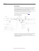
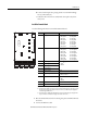
Trigger Isolation Jumpers
These jumpers cause the four trigger inputs to be isolated or non-isolated.
Non-isolated means the common of the trigger input can be connected to the
common of the Enwatch unit. With a jumper removed, the trigger is isolated.
The following table describes the jumper positions.
Mode Jumper Position
External trigger 1 isolated 17 Out
External trigger 1 non-isolated 17 In
External trigger 2 isolated 18 Out
External trigger 2 non-isolated 18 In
External trigger 3 isolated 19 Out
External trigger 3 non-isolated 19 In
External trigger 4 isolated 20 Out
External trigger 4 non-isolated 20 In
IMPORTANT
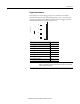
If an external sensor is powered from pin 1 of the external trigger terminals, the
jumper corresponding to the trigger channel must be inserted to provide a ground
return path for the sensor power.
33
22
1
33
22
1
33
22
1
33
22
1
17
18
19
20