
Owner's manual


Rockwell Automation Publication GMSI10-IN001A-EN-P - May 2013
8 Enwatch Unit
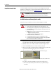
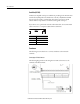
Wire the Enwatch Unit
For optimum performance, use shielded cables for all connections to the Enwatch
unit. For sensors such as accelerometers, connect the screens on the cables to
chassis ground at only one point. The optimal place for this is inside the Enwatch
enclosure and eight ground terminals are provided for this purpose. Connect the
screen at only one end; do not connect to ground at both ends.
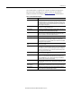
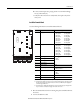
Analog Input Configuration
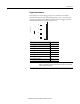
Each channel (16 total) has a 3-way header associated with it. These are labeled
with the channel number and ‘A’ or ‘B’. The three jumper options and couplings
are the following.
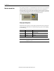
Coupling Fitted to Position Description
ICP x A
(1)
(1) Where x is the channel number, 1-16.
ICP power (nominal 24 V at 3.6 mA constant current for
transducer powering)
DC x B
(1)
DC coupled
AC Not Fitted AC coupled
IMPORTANT
The -3dB point of the high-pass coupling for the ICP interface and AC Coupled
configuration is 0.07 Hz.
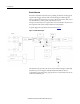
Earth Ground Terminal Strip
Mains Power Input and
Earth Ground Terminals