Installation Instructions Enwatch Unit Catalog Number EK-44750C Topic Page Important User Information 2 Enwatch Unit Overview 3 Install the Enwatch Unit 6 Wire the Enwatch Unit 8 Apply Power 12 Network Configuration 13 Monitoring and Troubleshooting 15 Enwatch Measurement Capabilities 17 Configure and Enwatch Board with Emonitor Software 25 Add an Enwatch Unload Station 25 Specifications 31 Additional Resources 32
Enwatch Unit Important User Information Solid-state equipment has operational characteristics differing from those of electromechanical equipment. Safety Guidelines for the Application, Installation and Maintenance of Solid State Controls (publication SGI-1.1 available from your local Rockwell Automation sales office or online at http://www.rockwellautomation.com/literature/) describes some important differences between solid-state equipment and hard-wired electromechanical devices.
Enwatch Unit 3 Enwatch Unit Overview The following sections give an overview of the hardware and electrical components of the Enwatch® unit. Hardware Overview The Enwatch unit contains a printed circuit board and power supply on a mounting base plate and housed in a metal enclosure. Use the key on the door of the enclosure to access the enclosure. The unit is pre-wired with mains input terminals connected to an internal 24V power supply. The power supply and internal wiring are fitted to a mounting base.
Enwatch Unit Electrical Overview Enwatch is a distributed network system providing 16 channels of analog inputs together with 4 trigger channels. The unit includes signal conditioning and analog to digital conversion. It lets you connect 16 two-wire ICP or other sensors into your Emonitor® Online system. Each Enwatch unit is a microprocessor-based system, complete with a network controller that carries out data acquisition tasks as directed by an Emonitor unload station.
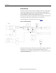
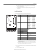
Enwatch Unit 5 The circuit board is a completely self-contained, 16-channel analog input to Ethernet interface, including power regulation and local communication facilities. Each block of the diagram in Figure 1 on page 4 is described below. Table 1 - Electrical Block Descriptions Block Description ICP interface Each of the 16 channels has its own ICP interface that is capable of powering a typical two-wire ICP transducer. The nominal voltage is 24 V with a constant current of 3.6 mA.
Enwatch Unit Install the Enwatch Unit Use these installation instructions to install, test, and configure the Enwatch hardware. For information on collecting data with the Enwatch unit, refer to the Emonitor User's Guide, publication EMONTR-UM001. ATTENTION: If the Enwatch unit is used in a manner not specified by Rockwell Automation, the protection provided by the Enwatch unit may be compromised.
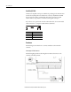
Enwatch Unit 7 d. Connect mains input wires, paying attention to terminal markings live (L) and neutral (N). e. Verify that all connections are safely made, then replace the yellow safety cover. Install the Enwatch Board Use the following information to install the Enwatch board. 11 TX RX LK OB 12 9 10 8 7 _ Connector Description Pin No.
Enwatch Unit Wire the Enwatch Unit For optimum performance, use shielded cables for all connections to the Enwatch unit. For sensors such as accelerometers, connect the screens on the cables to chassis ground at only one point. The optimal place for this is inside the Enwatch enclosure and eight ground terminals are provided for this purpose. Connect the screen at only one end; do not connect to ground at both ends.
Enwatch Unit 9 Trigger Isolation Jumpers These jumpers cause the four trigger inputs to be isolated or non-isolated. Non-isolated means the common of the trigger input can be connected to the common of the Enwatch unit. With a jumper removed, the trigger is isolated. The following table describes the jumper positions.
Enwatch Unit Serial Port (RS-232) An RS-232 compatible serial port is available for providing local communication with the board (independent of the Ethernet network). Only RXD and TXD lines are supported, and so a null modem cable must be used. An on-board software monitor is provided to communicate through the serial port. If you do not use a 9-pin female to female null modem cable, the recommended cable connection to a computer is defined in the table below.
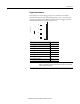
Enwatch Unit 11 Connecting a Coil-Based Velocity Sensor The following diagram shows the wiring from a coil-based velocity sensor to the terminals of the Enwatch unit. Connecting an Process DC Voltage Signal The following diagram shows the wiring from a process DC voltage signal to the terminals of the Enwatch unit.
Enwatch Unit Connecting a Magnetic Hall Effect Sensor The following diagram shows the external trigger wiring from a magnetic Hall effect sensor (magnetic interrupter) to the terminals of the Enwatch unit.
Enwatch Unit 13 Network Configuration Contact your IT department to obtain a unique IP address, Subnet Mask, and Gateway IP address (if available) for each Enwatch unit and record them here.
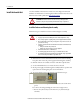
Enwatch Unit 7. Select 3 - Assign Host IP, and set your Enwatch unit to one of your plant specific IP addresses (press Esc if the IP address shown is the correct one). Please note, you must enter all of the digits of the IP address, including zeros that are placeholders. For example, the IP address 192.168.1.2 must be entered as 192.168.001.002. 8. Select 4 - Assign Host UDP Port, and set it to 4242. This is the default port number and cannot be any other number. 9.
Enwatch Unit 15 Monitoring and Troubleshooting Use the following sections to help you monitor and troubleshoot the Enwatch unit. On Board Monitor When you insert a jumper into the normal/monitor mode connector (21), the Enwatch unit operates in its internal monitor mode. This enables you to change the IP address as well as modify other options. 21 Mode Connector 21 Normal Jumper out Monitor Jumper in To invoke monitor mode, complete these steps. 1.
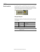
Enwatch Unit Status Indicators These status indicators indicate the status of the Ethernet communication. TX RX LK OB Name Description TX Flashes green when a response is sent from the board. Note: If the Enwatch board has an IP address that is not compatible with the network the TX indicator will not blink. RX Flashes green when a message is received. LK Solid green when the Enwatch unit is connected the network. Otherwise the indicator is off.
Enwatch Unit 17 Enwatch Measurement Capabilities This section lists the measurement capabilities of the Enwatch unit. Table 2 - Enwatch measurement capabilities Product Feature Capability Signal Control Raw input signal Integrated input signal via HP filter Hp filter input signal gSE 200 Hz input signal gSE 5000 Hz input signal Bias Voltage Combining measurements in the Enwatch driver The Enwatch driver can combine measurements at the same location in the Emonitor software.
Enwatch Unit Table 2 - Enwatch measurement capabilities Product Feature Capability Sample length Multiple of 256 bytes, maximum sample 32768 bytes if no trigger, 16384 bytes with pre-trigger (not used in first version of Enwatch) Filter settling time HP 0.36 Hz HP 2.67 Hz HP 5.3 Hz HP 23.8 Hz Integrator HP 0.36 Hz Integrator HP 2.67 Hz Integrator HP 5.3 Hz Integrator HP 23.8 Hz gSE 200 Hz gSE 5 kHz Core Time constant of 0.03 seconds Time constant of 0.006 seconds Time constant of 0.
Enwatch Unit 19 Table 2 - Enwatch measurement capabilities Product Feature Capability Bias voltage reading When you define a process measurement of DC in the Emonitor software, the Enwatch unit reads the transducer bias voltage. 24V means open circuit, 10V is OK. Maximum number of averages that can be supported Number of samples required: Lines x 2.56 + lines x 2.56(#avg -1) x (1 -%overlap) Max number of samples per configuration: 32768 Max number of averages = ((32768 / (lines x 2.
Enwatch Unit Setting Up Sample Measurements This section gives examples of setting up measurement definitions in the Emonitor software. DC or Other Numeric Measurements Suppose you have a transducer with an output of -2 V to 2 V and a linear scale from -10° F to 100° F.
Enwatch Unit 21 2. Select Setup>Transducer to select the “Temperature” transducer in the collection specification. 3. In the Emonitor software, define a numeric measurement definition with the temperature units and the “Temperature” collection specification. Transducer Bias Reading The Enwatch board can take transducer bias readings; however, this is not a transducer check function that detects transducer failure before taking data.
Enwatch Unit 4. Select Setup>Calibration to select “Bias Voltage” as the input type for this transducer. Set the calibration to 1000 and the offset to 0. 5. Click OK. 6. Select Setup>Collection to define a new collection specification. Select “Transducer Check” as the transducer. 7. In the Emonitor software, define a numeric measurement definition with V DC units and the “Transducer Bias” collection specification.
Enwatch Unit 23 Order Normalized Measurements Enable order normalized measurements in the collection specification. 1. In the Emonitor software, select Setup>Collection. 2. Edit an existing collection specification or create a new one. 3. Verify that Order normalization is checked. The Enwatch unit then finds the machine speed and applies it to the number of orders to select the proper sampling rate before collecting data.
Enwatch Unit DSP Functions in the Enwatch Driver The Enwatch unit takes only time domain data and returns that data to the host software. All DSP functions are done by the host driver. In this way, the firmware can focus on data collection speed. Because the Enwatch board does not handle calculating the average time waveform, the host driver software must tell the Enwatch unit to collect a time waveform of sufficient length to calculate the average.
Enwatch Unit 25 Configure and Enwatch Board with Emonitor Software The Enwatch unit is specially designed to operate over an Ethernet connection. Each Enwatch unit has a unique IP address that can be changed through the RS232 port inside the unit. Ideally, one Enwatch unload station can serve an unlimited number of Enwatch units. However, to improve unload speed, multiple Enwatch unload stations are suggested. Each Enwatch unit has 16 vibration channels and 4 tachometer channels.
Enwatch Unit 5. Enter a Name and click OK. 6. Select the new data source, and click Edit. The Setup window opens. 7. Right-click Emonitor Online and select Insert. The Insert Unload Station window opens. 8. Select Enwatch Unload Station and click Next. The General tabs opens. 9. Enter the IP address of the computer on which the Online Data Management Console is installed (not the IP address of the Enwatch board), or click Browse to find the computer name. 10.
Enwatch Unit 27 Add Enwatch Units 1. Right-click the Enwatch Unload Station and select Insert. 2. Click the Insert and instrument radio button and click Next. 3. Select the type of Enwatch unit you are installing and click Next. The Enwatch window opens. Configuring the Enwatch Unit 1. On the General tab, enter a Description and the IP address of the Enwatch unit.
Enwatch Unit 2. Select the Channel tab. This tab is used to map the Enwatch channel to the measurement point in the database. 3. On the Channel tab, double-click the first square to the left of the channel number. A connection to the database opens and the hierarchy tree from the Emonitor database is displayed. 4. Expand the tree and select the measurement point to which you want to map the Enwatch channel and click OK. The machine name and location are populated.
Enwatch Unit 29 The Enwatch unit appears under the Enwatch Unload Station. Save the Machine Speed with a Spectrum To add or edit an Enwatch unit, click the Trigger Channel tab. The Timeout is defined in seconds (the default is 5 seconds). The Number of pulse per rev default is 1 pulse per revolution. Click the Channel tab and assign the correct Trigger channel to the vibration channel. This example uses trigger channel 1 for the measurement on input channel 1.
Enwatch Unit Validating Enwatch Measurements To add or edit an Enwatch unit, you can set up a validation function to allow the driver to check the channel’s data before updating the database. This function can be used to filter unwanted data when the machine is not running, or when some other parameter is not within the correct bounds. Click the Channel tab, then double-click in the Validate column to set up the validation parameters. You can reference any channel in any order.
Enwatch Unit 31 Specifications Enwatch Technical Specifications Product Feature Inputs Specification Number of Channels 16 vibration and 4 tachometer (synchronizer) Voltage Protection Protects against over-voltage (channel auto-switch off) 2000 V ESD protection Input Impedance 1 M Ranges ±10 mV… ±10 V, 7 ranges (software selectable) ICP Interface 3.
Enwatch Technical Specifications Product Feature Specification Mechanical Protection NEMA 4, IP66 Environmental Temperature -10 to 70° C Humidity 80% for temperatures up to 31 ºC, decreasing linearly to 50% at 40 ºC Relative Humidity maximum 80% noncondensing Power Supply 100…240V AC, 50 or 60 Hz Power Consumption 12 W maximum Network Ethernet Medium 10BASE-T Connectors Weidmuller terminal blocks, 500V AC Speed 10 Mbits/sec Isolation 1000 Vrms (1) Power Communication (1) Mains s