Direct Drive Technology Demonstration Machine Quick Start
Important User Information Solid state equipment has operational characteristics differing from those of electromechanical equipment. Safety Guidelines for the Application, Installation and Maintenance of Solid State Controls (publication SGI-1.1 available from your local Rockwell Automation sales office or online at http://literature.rockwellautomation.com) describes some important differences between solid state equipment and hard-wired electromechanical devices.
Table of Contents Preface About This Publication . . . . . . . . . . . . . . . . . . . . . . . . . . . . . . . . . . . . . . 5 Audience . . . . . . . . . . . . . . . . . . . . . . . . . . . . . . . . . . . . . . . . . . . . . . . . . . 5 Parts List . . . . . . . . . . . . . . . . . . . . . . . . . . . . . . . . . . . . . . . . . . . . . . . . . . 5 Chapter 1 Install the Direct Drive Technology Demonstration Machine Introduction . . . . . . . . . . . . . . . . . . . . . . . . . . . . . . . . . . . . . . .
Table of Contents 4 Publication PMC-QS002B-EN-P - October 2008
Preface About This Publication Use this quick start to setup the Direct Drive Technology Demonstration Machine. This quick start describes the necessary tasks to install and run this demonstration machine. Audience This quick start is for anyone who will be setting up Direct Drive Technology Demonstration Machine for demonstration purposes only. Parts List This quick start uses the following hardware.that is shipped with the demonstration machine.
Preface 6 Publication PMC-QS002B-EN-P - October 2008
Chapter 1 Install the Direct Drive Technology Demonstration Machine Introduction In this chapter, you will install Direct Drive Technology Demonstration Machine.
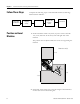
Chapter 1 Install the Direct Drive Technology Demonstration Machine Follow These Steps Position and Level Machine Position and Level Machine Complete the following steps to install the Direct Drive Technology Demonstration Machine. Remove Shipping Clamps Install Signs Assemble Computer and Computer Stand Make Connections 1. Position machine within 2 m (6.6 ft) of power source and with 1 m (3.3 ft) clearance in the front, back and right side of the machine.
Install the Direct Drive Technology Demonstration Machine Chapter 1 3. Adjust the leveling feet so the machine is visually level. Casters not shown Remove Shipping Clamps 1. Cut the tie wrap holding the power cable to the back door handle. 2. Remove the 8M Socket Head Cap Screw (SHCS) (X2) and the 6M SHCS (X4) from the bridge brace and remove brace.
Chapter 1 Install the Direct Drive Technology Demonstration Machine 3. Remove the cantilever axis shipping brackets at each end of the stage. a. Remove the 8M SHCS and washers from the bridge riser. b. Loosen but don’t remove the 6M SHCS from the stage. c. Push the stage forward and slide the bracket off the stage.
Install the Direct Drive Technology Demonstration Machine Chapter 1 4. Remove the shipping bracket from each carriage on the dual stage and from the cantilevered axis carriage. a. Loosen but don’t remove the 3M SHCS. b. Back off the 6M SHCS until they clear the carriage. c. Slide the shipping bracket off the end of the stage. 3M SHCS 6M SHCS There are two tie wraps that secure the LEU stage.
Chapter 1 Install the Direct Drive Technology Demonstration Machine Install Signs 1. Attach the Build It, Buy It, Customize It sign to the back of the bridge by aligning the Velcro strips. If adjustment is necessary do not bend the sign. It could be permanently damaged. 2. Attach the Direct Drive Technology sign to the front of the bridge by aligning the sign to the edge of the bridge. If adjustment is necessary do not bend the sign. It could be permanently damaged.
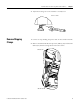
Install the Direct Drive Technology Demonstration Machine Assemble Computer and Computer Stand Chapter 1 1. Insert the uncapped end of pole in wheel base. 50 mm (2 in.) Pole Wheel Base 2. Loosen the 4M BHCS on the back of the computer monitor and slide into the keyholes of the Centris bracket and tighten all four screw. Centris Bracket M4 BHCS (X4) 3. Attach the swing arm keyboard assembly on to the post of the pole clamp.
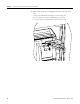
Chapter 1 Install the Direct Drive Technology Demonstration Machine Make Connections 1. Attach the keyboard USB and mouse infrared receiver to the Velcro on the support arm with the sensor side towards the keyboard. 2. Connect the USB and mouse cable to computer. 3. Connect computer power and network cable to the side of the machine. 4. Place mouse and keyboard on stand. Emergency Stop, Stop, Run Buttons Main Power Switch Keyboard and Mouse Infrared Receiver Network Cable Computer Power Cord 5.
Chapter 2 Using the Direct Drive Technology Demonstration Machine Introduction In this chapter, you will start the Direct Drive Technology Demonstration Machine and learn how to control it using the hardware buttons and the RSLogix Software application.
Chapter 2 Using the Direct Drive Technology Demonstration Machine Follow These Steps Complete the these steps to start the machine and the application software. Machine Start Up Machine Start Up Start Computer Application Machine Shut Down Follow these sequence to start the machine. 1. Close the back door. 1. Open the front door. a. Turn the laser pointer so the ON button is perpendicular to the carriage. b. Push the laser pointer down to turn it on. c. Tighten the hold down screw. d.
Using the Direct Drive Technology Demonstration Machine Start Computer Application Chapter 2 Machine motion can run without running the PC. To control the machine using the computer interface follow these steps. 1. Apply power to the computer. 2. Enter appropriate user name and password combination. 3. Click the RSLogix5000 icon: MPAS-Hbot_V1.04 4. Minimize MPAS-Hbot_V1.04 5. Click the HMI with Anorad_Hbot_Demo icon.
Chapter 2 Using the Direct Drive Technology Demonstration Machine Using Push Button Switches and Door Interlock to Run the Machine The Run, Stop (yellow), Emergency Stop push button switches and the front door interlock can control this machine without the use of the computer interface. Emergency Stop (E-stop) To stop the machine immediately push the E-stop switch. Using the E-stop switch requires you to follow the Machine Start procedure to start motion.
Using the Direct Drive Technology Demonstration Machine Using the Application to Control the Machine Chapter 2 Once the machine is initialized using the hardware buttons it can be controlled with the computer touch screen. The machine must be connected to the computer via the ethernet cable and the computer must be running the RSLogix Software application. There are two virtual buttons displayed on the touch screen: Run and Pause. Run will start the motion immediately.
Chapter 2 20 Using the Direct Drive Technology Demonstration Machine Publication PMC-QS002B-EN-P - October 2008
Appendix A Specifications and Dimensions Introduction Environmental Specifications for the Direct Drive Technology Demonstration Machine This appendix provides power and environmental specifications for the Direct Drive Technology Demonstration Machine.
Appendix A 22 Specifications and Dimensions Publication PMC-QS002B-EN-P - October 2008
Rockwell Automation Support If you experience a problem with a Direct Drive Technology Demonstration Machine, please review the information that's contained in this quick start. You can also contact the following customer support number for help in getting machine up and running. United States Publication PMC-QS002B-EN-P - October 2008 24 Supersedes PMC-QS002A-EN-P May 2008 1.631.344.6600 Monday – Friday, 8 a.m. – 5 p.m. EST Copyright © 2008 Rockwell Automation, Inc. Printed in the USA.