DEVICENET SEMINAR LAB EXERCISES What’s in This Lab Use these DeviceNet Seminar lab exercises to familiarize yourself with the DeviceNet network. ! ATTENTION: Do not skip ahead! There is no race to finish the lab. No prizes will be awarded for the first people to finish. Please take your time and learn as much as you can.
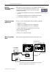
DeviceNet Seminar Lab Exercises Windows Conventions Used in This Manual This instruction manual assumes you are familiar with WindowsTM conventions including minimizing, maximizing, and closing windows using the button bar at the top right corner of the window. • Use the button with the horizontal bar to minimize the window but not close it. • Use the button with the square to maximize the window. • Use the button with the X to close the window.
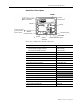
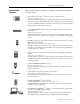
DeviceNet Seminar Lab Exercises 3 Demo Box 1 Description trunk line 4-position selector switch FLEX I/O adapter, terminal bases, and modules voltmeter T-Port tap power cord (can be used with 110V or 220V ac outlet) terminating resistor terminating resistor power switch drop line photoeye and reflector RediSTATION operator interface Demo Box 1 includes the following components.
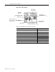
DeviceNet Seminar Lab Exercises Demo Box 2 Description DL10 Dataliner message display limit switch SLC processor with DeviceNet scanner DeviceLink discrete I/O 1305 ac drive power cord (can be used with 110V or 220V ac outlet) SMP-3 solid-state overload relay electric motor 1203-GK5 communication module Demo Box 2 includes the following components.
DeviceNet Seminar Lab Exercises Describing the Hardware 5 Here are the descriptions and the node numbers of the devices contained in the demo boxes. • An I/O chassis with an SLCTM 500 processor and a 1747-SDN scanner Scanner node number = 00 The scanner is the DeviceNet master coordinating all control data to and from all devices on the DeviceNet network. This DeviceNet data is transferred to and from the SLC 500 processor via M1/MO and discrete I/O transfers.
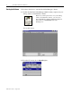
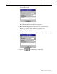
DeviceNet Seminar Lab Exercises Starting the Software Follow these directions to start the DeviceNet Manager software. 1. Double-click the DeviceNet Manager 3.001 icon that you placed on your desktop when you installed the software. Note: If you did not place the icon on your desktop when you installed the software, you can access DeviceNet Manager 3.001 from Windows Explorer in the directory c:\DNETMGR, file name Dnetmgr3.exe. You see this screen. 2. From the File menu, choose Open Project...
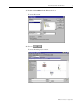
DeviceNet Seminar Lab Exercises 7 3. Double-click seminar in the Directories box. You see this screen. 4. Choose You see the main project screen. Publication 1787.6.
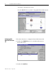
DeviceNet Seminar Lab Exercises Adding Devices Offline Follow these directions to add devices to your project offline. 1. In the Device List, double-click General Purpose Discrete I/O. 2. Double-click Allen Bradley Company, Inc. Tip: You can resize a window by grabbing the frame edge with the pointer (the pointer turns to a double arrow) and dragging the bar to the right or left. 3. Using the up- and down-arrow keys, scroll down to the second DeviceLink - mini to mini connector (Revision 2.1).
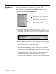
DeviceNet Seminar Lab Exercises 9 You see this screen. We will now edit the DeviceLink we just placed. 5. Make the following changes in the Edit Device From dialog box. A. Scroll down in the Node Address box and choose 5. B. Type in PROX234 for the Node Name. C. Type Proximity Sensor, Part in Position for the Node Description. 6. Choose for the changes to take effect. Publication 1787.6.
DeviceNet Seminar Lab Exercises You return to the main project screen. Note that PROX234 is now added to the graphical DeviceNet network. Configuring The DeviceLink Discrete I/O Follow these directions to configure the DeviceLink discrete I/O. 1. Double-click PROX234 (node 5) on the DeviceNet network. You see this screen. 2. Double-click On Filter. Publication 1787.6.
DeviceNet Seminar Lab Exercises 11 You see this screen. 3. Click the radio button (circle) next to 25 ms Filter. 4. Choose 5. Click Parameter 3R. You see this screen. The configuration is changed in the software but has not been saved to a file or to the DeviceLink discrete I/O itself. 6. Choose Publication 1787.6.
DeviceNet Seminar Lab Exercises You see this screen. Note: We will NOT be saving this new configuration now! In offline mode, the configuration can be stored to a file inside the personal computer running the software for future recall. 7. Choose You return to the main project screen. Publication 1787.6.
DeviceNet Seminar Lab Exercises Configuring the FLEX I/O Module 13 Follow these directions to configure the FLEX I/O module. 1. Double-click FLEX I/O (node 1) on the DeviceNet network. You see this screen. The FLEX I/O configuration screen is a custom application used to configure the various modules within the FLEX I/O rack. 2. Choose You see this screen. 3. Double-click the seminar directory. 4. Then double-click the network2 directory. 5. Click once on flexio.prf to highlight it. 6.
DeviceNet Seminar Lab Exercises You see this screen. This file has a previously stored configuration. Four modules displayed by name are in the module configuration field. 7. To display the module type by Allen-Bradley catalog number, click the radio button next to Catalog No. You see this screen. 8. To custom configure the 16-point discrete input module in slot 0 (1794-IB16), choose Publication 1787.6.
DeviceNet Seminar Lab Exercises 15 You see this screen. This screen allows you to enter the amount of input and output used by the 1794-IB16 along with other module-specific configurations. Delay constants can be chosen for each of two subgroups of the inputs (0-11 and 12-15). 9. Click once on the arrow next to the msec box for inputs 0-11 to highlight your choices. 10. Choose 32 msec. 11. Choose Publication 1787.6.
DeviceNet Seminar Lab Exercises You return to this screen. 12. To custom configure the 8-channel analog input module in slot 2 (1794-IE8), choose You see this screen. You can choose the analog mode configuration for each of the 8 channels on the module. 13. Click the arrow next to Channel 0. You see these choices. Publication 1787.6.
DeviceNet Seminar Lab Exercises 17 14. Click once on +/- 10 V. 15. To exit the 1794-IE8 Configuration screen, choose You see this screen. The I/O configuration box determines what will happen to the analog and discrete outputs in the FLEX I/O rack when there is a fault or idle condition on the DeviceNet network. An example of idle condition is when the PLC processor is placed in program mode. An example of fault condition is a broken communication line. 16.
DeviceNet Seminar Lab Exercises 17. Click once on Hold Outputs in Last State to select it. The 1794-ADN will now default to Hold Outputs in Last State if a fault is detected while the 1794-ADN is in Run mode. Note: We will NOT be saving this new configuration now! In future uses, once all modules are configured, the configuration needs to be saved. You would choose Yes to save the configuration to a file within this project.
DeviceNet Seminar Lab Exercises 19 You return to the main project screen. Configuring the Scanner Follow these directions to configure the 1747-SDN scanner. 1. Double-click the Master (node 0) on the DeviceNet network. You see this screen. This screen allows you to configure the 1747-SDN scanner’s operating parameters along with entering the scan list of what devices will be scanned on the network. Publication 1787.6.
DeviceNet Seminar Lab Exercises Notice that the project name is SEMINAR and the network name is NETWORK1. 2. Choose You see this screen. 3. Choose You see the main project screen. We will now build the scan list by dragging and dropping devices onto the Master device (node 0). Publication 1787.6.
DeviceNet Seminar Lab Exercises 21 4. Click PE101 (node 2) once to highlight it. While holding down the left mouse button, drag PE101 over to the master and drop it. Notice that PE101 now has a red square around it with a “0” next to the red square. 5. Repeat this step to add the other two devices on the DeviceNet network to the Master. When all devices are added to the Master you see this screen. 6. Choose Publication 1787.6.
DeviceNet Seminar Lab Exercises You see this screen. Automapping the Network Follow these directions to automap your DeviceNet devices’ data into the SLC-500 input and output I/O memory. 1. Choose to highlight all of the devices. 2. Choose You see this screen. 3. To start automapping, choose Publication 1787.6.
DeviceNet Seminar Lab Exercises 23 The software maps the devices and returns you to this screen. Notice that all three slave devices in the list have “Yes” in the active column as they are now active in the scan list and will communicate to the 1747-SDN scanner on the network. Also notice the “Yes” in the Mapped column, which is showing that data is currently mapped to and/or from the SLC-500. The “Yes” in the left column means that data is mapped from the device to the SLC-500.
DeviceNet Seminar Lab Exercises You see this screen. Notice that node 1 occupies words 1 through 11 of the discrete input area. This is the input data from the FLEX I/O node. You may need to scroll down to see I:1.11 on the screen. Notice that word I:1.0 is reserved for the module status register of the 1747-SDN (denoted above by the letter R). 5. Click the radio button next to Output in the Data Map section. You see this screen.
DeviceNet Seminar Lab Exercises 25 6. Return to Input by clicking on the radio button next to Input in the Data map section. 7. In the Device Select box, click once on the arrow to display your choices. 8. Choose PROX234 (node 5). You see this screen. Notice that nodes 2 and 5 share word 12 of the discrete input area where the input data from these devices will be put. 9. Click the radio button next to Data Entry in the Display Mode section.
DeviceNet Seminar Lab Exercises We will now direct the DeviceLink discrete I/O from the discrete input file into the M1 file area. 10. In the Map Data To box, click the arrow to display your choices. A. Choose M File. B. In that same row, change Word 12 in the M1:1 box to 0. C. Change Bit 8 to 0. 11. Choose Scroll up to see this screen. 12. Choose You return to this screen. Publication 1787.6.
DeviceNet Seminar Lab Exercises 27 13. Choose You see this screen. Note: We will NOT be saving this new configuration now! In future uses, once all of the data is mapped, the configuration needs to be saved. You would choose Yes to save the configuration to a file within this project. When online, the configuration can be both read and saved directly to the 1747-SDN scanner using the Save To and Load From buttons. 14. Choose You return to this screen. 15. Choose Publication 1787.6.
DeviceNet Seminar Lab Exercises You return to the main project screen. Going Online Follow these directions to go online with the DeviceNet network. Note: You should be at the main project screen with SEMINAR.PC3 at the top of the screen. 1. Click once on Network2. You see this screen. Publication 1787.6.
DeviceNet Seminar Lab Exercises 29 2. From the Utilities menu, choose Setup Online Connection... You see this screen. 3. Choose Publication 1787.6.
DeviceNet Seminar Lab Exercises You see this screen. Important: Your values should match those seen on this screen. 4. Choose ! Publication 1787.6.1 - August 1997 ATTENTION: In future uses, you need to make sure that all devices are set to the proper data rate. Attempting to go online at the wrong data rate may cause some or all devices on the network to fail.
DeviceNet Seminar Lab Exercises Building Your Network 31 Follow these directions to have the software build your network once you are online. 1. From the Utilities menu, choose Start Online Build... You see this message while Online Build is occurring. When the Online Build is finished, you see this screen. At this time it is not necessary to upload the 1747-SDN scan list over the network. The scan list will be loaded from a file later in the exercises. 2. Choose Publication 1787.6.
DeviceNet Seminar Lab Exercises You see the device list screen. We will now monitor and configure a few of these devices online. Configuring the Photoeye Online Follow these directions to configure the photoeye online. 1. Rotate the selector switch at the top of the demo box so that an amber 2 is illuminated on the front of the 1794-IB16 FLEX I/O module. 2. In the Device List, double-click on node_7, the Series 9000 Retroflective photoeye. Publication 1787.6.
DeviceNet Seminar Lab Exercises 33 You see this screen. 3. Double-click Parameter 2R. You see this screen. Notice that the green margin status indicator on the sensor is lit as the reflector is correctly aligned with the sensor. 4. Choose 5. Put your hand between the reflector and the photoeye. You will see that the setting on the software changes from On to Off. Also notice that the red light on the RediSTATION operator interface module goes on. Publication 1787.6.
DeviceNet Seminar Lab Exercises 6. Remove your hand from between the reflector and the photoeye. You will see that the setting on the software changes back from Off to On and the red light on the RediSTATION operator interface module goes off. The RediSTATION operator interface’s light is controlled from the SLC-500 processor using the status bit from the photoeye as an input into the 1747-SDN scanner. 7. Choose Stop Monitor. 8. Choose You return to this screen. Publication 1787.6.
DeviceNet Seminar Lab Exercises 35 Testing the Low-Margin Capability Low margin is determined by the sensor when it is not receiving enough light for optimum operation. The amber status indicator is lit but the green margin status indicator is not when in low margin mode. 1. Double-click Parameter 3R. Notice that the operating margin of the photoeye is OK. 2. Choose 3.
DeviceNet Seminar Lab Exercises You return to this screen. 7. Double-click Parameter 1. You see this screen. Notice the current Operate Mode is Light Operate. 8. Click the radio button next to Dark Operate. 9. Choose Notice that the RediSTATION operator interface’s red light goes on. The light will turn off if you put your hand between the photoeye and the reflector. This behavior is opposite of what it was before because you inverted the operate mode of the photoeye over the network.
DeviceNet Seminar Lab Exercises 37 10. To return operation to the original mode, click the radio button next to Light Operate. 11. Choose 12. Choose Important: All three lights on the photoeye should be illuminated and the RediSTATION operator interface’s red light off. Go back to step 7 if this is not true. 13. To exit the Device Configuration screen, choose You return to this screen.
DeviceNet Seminar Lab Exercises Monitoring and Configuring the AC Drive Online Follow these directions to configure the ac drive online. 1. Rotate the selector switch at the top of the demo box so that an amber 0 is illuminated on the front of the 1794-IB16 FLEX I/O module. 2. Double-click Node 4, the ac drive via the 1203-GK5 module. You see this screen in approximately 10 seconds. Important: If you do not see this screen, ask your instructor for assistance. 3. Double-click Parameter 1R.
DeviceNet Seminar Lab Exercises 39 4. Choose 5. Press the green Start button on the front of the RediSTATION operator interface. Notice that the output voltage displays a voltage around 56 V. Also notice that the 1305 ac drive displays At Speed and 15.00 Hz. Each time the green Start button is pressed, the voltage will increase or decrease by 56 V until it finally wraps around to 56 V again. Each time you press the green Start button, the speed display on the drive will also increase by 15.
DeviceNet Seminar Lab Exercises 9. Change the accel time to 20s by typing 20 in the value field. 10. Choose 11. Press the RediSTATION operator interface’s red Stop button. Now look at the front of the drive. 12. Press the RediSTATION operator interface’s green Start button. Notice that it took longer to reach 15.00 Hz due to the new accel time. 13. Press the RediSTATION operator interface’s red Stop button. 14. Important: Restore the accel time to 5s by typing 5 in the value field. 15.
DeviceNet Seminar Lab Exercises 41 You see this screen. 17.Choose You see this screen. Publication 1787.6.
DeviceNet Seminar Lab Exercises Configuring the 1747-SDN Scanner Online Follow these directions to configure the scanner online. 1. Double-click Node_ 0, the 1747-SDN scanner. You see this screen. 2. Choose You see this screen. 3. Choose Load From File. 4. Click once on seminar.sl4 to highlight it. Publication 1787.6.
DeviceNet Seminar Lab Exercises 43 You see this screen. 5. Choose You see this screen. 6. Choose Publication 1787.6.
DeviceNet Seminar Lab Exercises You see this screen. By using the device select field, you can view the mapping of each device into the data table inside the SLC-500 processor. Note: The RediSTATION, photoeye, and DeviceLink are all sharing the same data field. This shows the versatility of the DeviceNet Manager software for mapping device data. The scan list is the same as what is actually loaded in the 1747-SDN of your seminar.
DeviceNet Seminar Lab Exercises 45 8. Choose You see this screen. 9. Choose You see this warning screen. 10. Choose You return to this screen. Publication 1787.6.
DeviceNet Seminar Lab Exercises 11. Choose You return to the project screen. 12. Close the project window by clicking the button with an X in the upper right corner of the project window. Important: Click the lower X, so as to close the project but not DeviceNet Manager software. You see this screen. 13. Choose Publication 1787.6.
DeviceNet Seminar Lab Exercises 47 You return to the main DeviceNet Manager screen. Note that you are still online. Using Network Who Network Who provides you with a summary of the node address, manufacturer of the device, device type, product name and serial number for each device on the network, plus the total number of devices identified. Important: You must be online to select Network Who. 1. From the Who menu, choose Network Who. This screen appears while Network Who operates. Publication 1787.
DeviceNet Seminar Lab Exercises When it is finished scanning the network, you see this screen. 2. Click once on Node_ 0 to highlight it. 3. Choose You see this screen. Notice the details that can be accessed directly from the devices, such as firmware revisions and serial numbers. Publication 1787.6.
DeviceNet Seminar Lab Exercises 4. To scroll through the list, choose 49 or 5. Once you have finished, choose You return to this screen. You could also configure a device from Network Who by choosing This method is the same as double clicking an icon on the DeviceNet network as we did earlier in this seminar in the Configuring Devices Offline section. 6. Choose Publication 1787.6.
DeviceNet Seminar Lab Exercises You see this screen. 7. Choose You return to the main DeviceNet Manager screen. Using Mini Who Mini Who is a quick way to determine devices on the network by node number and the total number of devices found on the network. Important: You must be online to select Mini Who. 1. From the Who menu, choose Mini Who. Publication 1787.6.
DeviceNet Seminar Lab Exercises 51 You see this screen. You can wait for Mini Who to finish scanning the network, which doesn’t take long, or you can choose 2. Choose You return to this screen. Using Node Commissioning Node Commissioning allows you to change the node address and data rate of individual devices. This is normally done when a network is initially assembled. Devices out of the box will have node 63 and 125 k baud as defaults. Important: You cannot be within a project to commission nodes.
DeviceNet Seminar Lab Exercises 1. From the Utilities menu, choose Node Commissioning... You see this screen. 2. In the Current Device Settings box, scroll the list and choose node 7 (the photoeye). Publication 1787.6.
DeviceNet Seminar Lab Exercises 53 3. In the New Device Settings box, scroll the list and choose node 55. 4. Choose Notice that the RediSTATION operator interface’s red light starts blinking, the DL10 Dataliner display shows a PHOTO OFF DEVICENET message, and the scanner display alternatively blinks between 72 and 07. Also, the green status indicator on the photoeye should be blinking green.
DeviceNet Seminar Lab Exercises 5. In the Current Device Settings box, scroll the list and choose node 55. 6. In the New Device Settings box, scroll the list and choose node 7. 7. Choose Notice that the RediSTATION operator interface’s red light stops blinking, the DL10 Dataliner display returns to the normal message, the scanner displays 00, and the photoeye’s communications status indicator turns solid green. 8. Choose Publication 1787.6.
DeviceNet Seminar Lab Exercises 55 You return to the main DeviceNet Manager screen. Minimize the software by clicking the button with the horizontal bar in the upper right corner of the window. Important: Do not close the software. Only minimize it. Starting RSLogix 500 Software The next section of the lab uses RSLogix 500 programming software. 1. Double-click the RSLogix 500 icon on your desktop to start the program.
DeviceNet Seminar Lab Exercises You see this screen. 2. From the Comms menu, choose Go Online. You see this screen. Publication 1787.6.
DeviceNet Seminar Lab Exercises 57 3. From the navigation window in the left frame, scroll down from Project to Program Files and choose LAD 155 by double clicking. You see this screen in the right frame. You see the rungs of ladder logic. Monitoring Inputs Follow these directions to monitor the inputs using RSLogix 500 software. 1. From Data Files, choose I1 by double clicking. Publication 1787.6.
DeviceNet Seminar Lab Exercises You see this screen. Notice that Word I:1.1 format (shown on page 44 and again here for reference), is shared by nodes 7, 10 and 15. Publication 1787.6.
DeviceNet Seminar Lab Exercises 59 2. Rotate the selector switch completely counter-clockwise until an amber 0 is illuminated on the 1794-IB16. 3. Press and hold the Start button until you see that data location I:1.1, bit 9 changes to a 1. 4. Release the Start button. 5. Press and hold the Stop button until you see that data location I:1.1, bit 8 changes to a 1. 6. Release the Stop button. 7. Press and release the Start button. Notice the red light on the RediSTATION operator interface goes on. 8.
DeviceNet Seminar Lab Exercises gently and turning the light bulb counter-clockwise. Notice in data location I:1.1 that bit 12 changes to a 1. 9. Replace the light bulb by gently pressing it into its socket and turning it clockwise. Bit I1:1/12 goes to a 0. 10. Replace the red lens. Note: This diagnostic only works if the RediSTATION light is on (the Start button has been pushed). 11. Press the RediSTATION operator interface’s Stop button. 12.
DeviceNet Seminar Lab Exercises 61 Notice as you rotate the selector switch clockwise and counter-clockwise, one of bits 0 through 3 in data location I:1.4 goes to a 1 depending on which position the switch is in. 16. Close the Data File by clicking the button with an X in the upper right corner of the Data File window. You return to this screen. Monitoring Outputs Follow these directions to monitor the outputs using RSLogix 500 software. Publication 1787.6.
DeviceNet Seminar Lab Exercises 1. From Data Files, choose O0 by double clicking. You see this screen. 2. Rotate the selector switch counter-clockwise until an amber 0 is illuminated on the 1794-IB16. 3. Press the RediSTATION operator interface’s Start button. Notice in O:1.1 that bit 0 goes to a 1 and the RediSTATION operator interface’s light is on. This bit is directly mapped to the RediSTATION operator interface’s light. When O:1.
DeviceNet Seminar Lab Exercises 63 Notice in O:1.1, that bit 0 changes to a 0. 5. Rotate the selector switch clockwise until an amber 1 is illuminated on the 1794-IB16. Notice the voltmeter on the demo box swings continuously from 0 V to 10 V and back to 0 V. 6. In the Radix selection box, choose Hex/BCD. You see this screen. Notice that output word O:1.2 is the analog data that is being sent to channel 0 of the 1794-OE4 card and ultimately to the voltmeter. 7.
DeviceNet Seminar Lab Exercises You return to this screen. Monitoring the AC Drive Data Follow these directions to monitor the ac drive data using RSLogix 500 programming software. 1. From Data Files, scroll down the list and choose N153. Publication 1787.6.
DeviceNet Seminar Lab Exercises 65 You see this screen. Notice the value in N153:0 is 8201, which is mapped to the ac drive command register. Notice the value in N153:1 is 0, which is mapped to the ac drive speed register. 2. Rotate the selector switch counter-clockwise until an amber 0 is illuminated on the 1794-IB16. 3. Press the RediSTATION operator interface’s Start button. Notice in N153:0, that the value changes to an 8218 (forward direction) or 8234 (reverse direction).
DeviceNet Seminar Lab Exercises Also notice that the value in N153:1 increments by 8191 for every push of the RediSTATION operator interface’s Start button. Every increase of 8191 in the drive speed register commands the ac drive to increase by 15.00 Hz. Pressing the RediSTATION operator interface’s Stop button loads a value of 8201 into N153:0, which commands the ac drive to stop.
DeviceNet Seminar Lab Exercises Monitoring with the Device Failure Table 67 Follow these directions to monitor the device failure table using RSLogix 500 software. 1. From Data Files, scroll down the list and choose N152 by double clicking. You see this screen. 2. Change the radix to binary format. Publication 1787.6.
DeviceNet Seminar Lab Exercises You see this screen. Notice that all bits between N152:0, bit 0, and N152:3, bit 15, are 0s. These 64 bits are the device failure bits forming a bitmask with each bit representing a node between 0 and 63 decimal. 3. Disconnect the photoeye’s drop line from the trunk line. You see this screen. Verify that N152:0, bit 7, changes to a 1. Notice that 72 and 07 are alternatively flashing on the node address display of the scanner.
DeviceNet Seminar Lab Exercises 69 You return to this screen. Monitoring a Rung Follow these directions to monitor a rung on the ladder logic display using RSLogix 500 programming software. 1. Scroll down the LAD 155 screen to rung 0060. Scrolling to 0060 advances you to rung 60, which controls bit O:1/16. Bit O:1/16 is mapped to the RediSTATION operator interface’s light. 2. Rotate the selector switch until an amber 3 is illuminated on the 1794-IB16. Publication 1787.6.
DeviceNet Seminar Lab Exercises Notice that the I:1/67 contact is green. Pressing the RediSTATION operator interface’s Start button or Stop button causes bits I:1/24 or I:1/ 25 to go green. This energizes O:1/16, which is represented by the coil turning green, and turns on the RediSTATION operator interface’s light. 3. Rotate the selector switch until an amber 2 is illuminated on the 1794IB16. Notice that the I:1/66 contact is green.
DeviceNet is a trademark of the Open DeviceNet Vendor Association (ODVA). Allen-Bradley is a trademark of Rockwell Automation, a core business of Rockwell International Corporation. The following are trademarks of Rockwell Automation: SLC, FLEX I/O, SMP-3, DeviceNetManager, DeviceLink, PHOTOSWITCH, RediSTATION. RSLogix 500 is a trademark of Rockwell Software, Inc. Windows is a trademark of Microsoft Corporation.