
Manual

Using Multi-Drive Mode
8-9
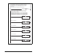
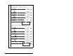
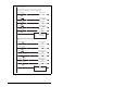
Figure 8.6 – Main Routine
0
Local:3:O.CommandRegister.Run
1
Copy File
Source Local:3:I.Data[0]
Dest DriveInputImage[0]
Length 10
COP
2
Jump To Subroutine
Routine Name Drive0
JSR
3 Jump To Subroutine
Routine Name Drive1
JSR
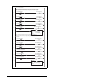
4
Jump To Subroutine
Routine Name Drive2
JSR
5
Jump To Subroutine
Routine Name Drive3
JSR
6 Jump To Subroutine
Routine Name Drive4
JSR
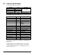
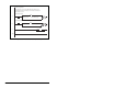
ControlLogix MultiDrive example program with an MD65 drive at node address 1.
Four MD65/MD60 drives are daisy-chained to the main MD65 drive via their RJ45
ports (RS-485). In this mode, up to FIVE MD65/MD60 drives can exist on ONE
DeviceNet node.
This rung enables the scanner (changes the scanner to RUN mode).
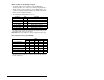
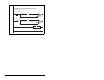
This section retrieves the Logic Status and Feedback data for all five drives from
the scanner, and moves it to specific INT tags for use elsewhere in the ladder
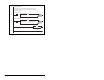
program. The input image is as follows:
Drive Input Image (0) and Drive Input Image (1) = Drive 0 Logic Status and Feedback
Drive Input Image (2) and Drive Input Image (3) = Drive 1 Logic Status and Feedback
Drive Input Image (4) and Drive Input Image (5) = Drive 2 Logic Status and Feedback
Drive Input Image (6) and Drive Input Image (7) = Drive 3 Logic Status and Feedback
Drive Input Image (8) and Drive Input Image (9) = Drive 4 Logic Status and Feedback
Drive 0 controls subroutine.
Drive 1 controls subroutine.
Drive 2 controls subroutine.
Drive 3 controls subroutine.
Drive 4 controls subroutine.