
Manual

8-8
DeviceNet Communications Module
8.6 ControlLogix Example
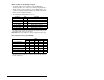
The following common Tags are used:
The following Tags are used for Drive 0:
The same type of Tags are also used for Drive 1 through Drive 4.
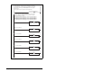
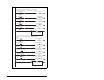
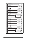
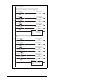
Main Routine
The Main Routine tells the 1756-DNB scanner to run, reads the
network Input Image from the scanner, calls the various drive
control subroutines, and writes the network Output Image to the
scanner. See figure 8.6.
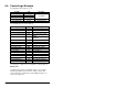
Tag Name Type Description
Local : 3 : I AB: 1756_D...
1756-DNB I/OLocal : 3 : O AB: 1756_D...
Local : 3 : 5 AB: 1756_D...
Drive Input Image INT [10] Input Image Table
Drive Output Image INT [10] Output Image Table
Tag Name Type Description
Drive 0 Command Stop BOOL Logic Command bit 0 (STOP)
Drive 0 Command Start BOOL Logic Command bit 1 (START)
Drive 0 Command Jog BOOL Logic Command bit 2 (JOG)
Drive 0 Command Clear Faults BOOL Logic Command bit 3 (CLEAR
FAULTS)
Drive 0 Command Forward BOOL Logic Command bit 4
(FORWARD)
Drive 0 Reference INT Speed Reference
Drive 0 Status Ready BOOL Logic Status bit 0 (READY)
Drive 0 Status Active BOOL Logic Status bit 1 (ACTIVE)
Drive 0 Status Forward BOOL Logic Status bit 3 (FORWARD)
Drive 0 Status Faulted BOOL Logic Status bit 7 (FAULT)
Drive 0 Status At Reference BOOL Logic Status bit 8 (AT SPEED)
Drive 0 Feedback INT Speed Feedback
Perform Parameter Read 0 BOOL Initiates the parameter read
Parameter RD Value 0 INT Read value of the parameter
Parameter RD Message 0 MESSAGE Get_Attribute_Single (Read)
Perform Parameter Write 0 BOOL Initiates the parameter value
Parameter WR Value 0 INT Write value to the parameter
Parameter WR Message 0 MESSAGE Set_Attribute_Single (Write)