
Manual

Using Multi-Drive Mode
8-7
Module Settings for the Example Program
• The Mode Jumper on the module is set to the Multi-Drive
operation position. See section 3.2, Commissioning the Module.
• All DIP switches on the module are set to CLOSED (all 0s). See
section 3.2, Commissioning the Module. The actual node address
will be set via a software parameter.
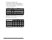
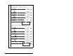
• The following module parameters are set:
Important: Drive node addresses change only after a power cycle.
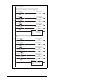
Drive Settings for the Program Example
Parameter Value Description
02 - (DN Addr Cfg) 1 DeviceNet node address
15 - (DSI I/O Cfg) 4 “Drives 0-4” — 5 drives on 1 node
17 - (Drv 0 Addr)
1
1 Modbus address of Drive 0
18 - (Drv 1 Addr) 2 Modbus address of Drive 1
19 - Drv 2 Addr) 3 Modbus address of Drive 2
20 - (Drv 3 Addr) 4 Modbus address of Drive 3
21 - (Drv 4 Addr) 5 Modbus address of Drive 4
1
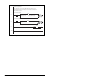
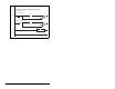
The settings for these parameters must match the parameter A104 (Comm
Node Addr) settings in the respective drives.
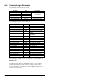
Parameter
Value
Drive 0 Drive 1 Drive 2 Drive 3 Drive 4
P36 - (Start Source) 5 5 5 5 5
P38 - (Speed Reference) 5 5 5 5 5
A103 - (Comm Data Rate) 4 4 4 4 4
A104 - (Comm Node Addr)
1
12 345
A105 - (Comm Loss Action) 0 0 0 0 0
A106 - (Comm Loss Time) 5 5 5 5 5
A107 - (Comm Format) 0 0 0 0 0
1
The settings for these parameters must match the respective parameter
settings in the module (parameter 17 (Drive 0 Address) through parameter
21 (Drive 4 Address)).