
Manual


8-4
DeviceNet Communications Module
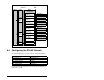
8.3 Understanding the I/O Image
The DeviceNet specification requires that the terms
input
and
output
be defined from the scanner’s point of view. Therefore,
Output I/O is data that is output from the scanner and consumed by
the DeviceNet module. Input I/O is status data that is produced by
the module and consumed as input by the scanner. The I/O image
table will vary based on the:
• Configuration of the Mode Jumper (J2) on the module and
parameter 15 (DSI I/O Cfg). The image table always uses
consecutive words starting at word 0.
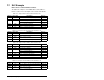
Figure 8.5 illustrates the Multi-Drive I/O image with 16-bit words.
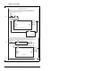
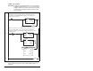
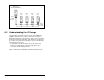
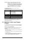
Figure 8.4 – AK-U0-RJ45-TB2P Connector Wiring Diagram
MD65 Drive
with MDCOMM-DNET
Drive
#2
Drive
#3
Drive
#4
Drive
#5
120 Ω
¼ Watt
Resistor
120 Ω
¼ Watt
Resisto
r