
Manual


6-10
DeviceNet Communications Module
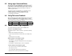
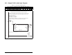
Figure 6.7 – Sample SLC Ladder Logic Program (continued)
0006
B3:0
4
Node 1
Forward
Command
O:1
21
1747-SDN
Node 1
Logic Command
REVERSE
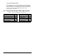
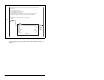
This rung controls the Reference for the MD65 drive. N7:0 would be controlled
elsewhere in the user program. Note that the Reference for the MD65 drive is set
in Hz and not in engineering units. For example, "300" equates to 30.0 Hz
(the decimal point is always implied).
0007
MOV
Move
Source N7:0
300<
Dest O:1.2
300<
MOV
Node 1
REFERENCE
(Hz)
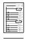
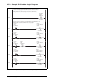
This section of rungs displays the Logic Status bits for the MD65 drive. The B3:1
bits would be used elsewhere in the user program.
0008
I:1
16
1747-SDN
Node 1
Logic Status
READY
B3:1
0
Node 1
READY
0009
I:1
17
1747-SDN
Node 1
Logic Status
ACTIVE
B3:1
1
Node 1
ACTIVE
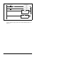
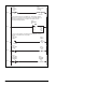
0010
I:1
19
1747-SDN
Node 1
Logic Status
ROTATING
FORWARD
B3:1
3
Node 1
ROTATING
FORWARD