
Manual


6-8
DeviceNet Communications Module
For the explicit message portion of this sample ladder program, see
figure 7.8.
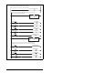
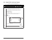
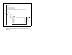
Figure 6.5 – Sample PLC-5 Ladder Logic Program (continued)
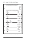
The BTR in this rung moves the drive control data to the scanner from the N10: data file in
the PLC, where:
N10:0 = Scanner Control word
N10:1 = MD65 (node 1) Logic Command
N10:2 = MD65 (node 1) Reference
Note that the Reference for the MD65 drive is set in Hz and not in engineering units.
For example, "300" equates to 30.0 Hz (the decimal point is always implied).
The scanner then sends the data to the drive over the network.
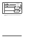
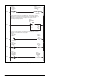
0002
BT20:1
EN
EN
DN
ER
BTW
Block Transfer Write
Module Type 1771-SDN DeviceNet Scanner Module
Rack 000
Group 0
Module 0
Control Block BT20:1
Data File N10:0
Length 62
Continuous No
Setup Screen
BTW