
Manual


Using I/O Messaging
6-7
6.5.2 Sample PLC-5 Ladder Logic Program
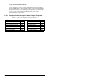
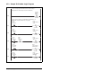
Table 6.2 – Control File for Block Transfers
EN ST DN ER CO EW NR TO RW RLEN DLEN FILE ELEM R G S
BT20:0000000000 62 0 9 0 0000
BT20:1000000000 62 0 10 0 0000
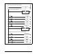
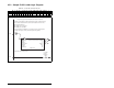
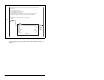
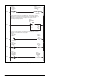
Figure 6.4 – Sample PLC-5 Ladder Logic Program
Sample PLC-5 program with an MD65 drive at DeviceNet node address 1.
The DeviceNet scanner gathers the drive status data via the network. The BTR in this rung
then moves the drive status data from the scanner to the N9: data file in the PLC, where:
N9:0 = Scanner Status word
N9:1 = MD65 (node 1) Logic Status
N9:2 = MD65 (node 1) Feedback
Note that the Feedback for the MD65 drive is received in Hz and not in engineering units.
For example, "300" equates to 30.0 Hz (the decimal point is always implied)
.
0000
BT20:0
EN
EN
DN
ER
BTR
Block Transfer Read
Module Type 1771-SDN DeviceNet Scanner Module
Rack 000
Group 0
Module 0
Control Block BT20:0
Data File N9:0
Length 62
Continuous No
Setup Screen
BTR
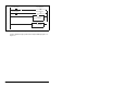
This rung enables the DeviceNet scanner.
0001
N10:0
0
1771-SDN
Scanner
Enable bit