
Manual


Using I/O Messaging
6-5
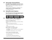
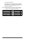
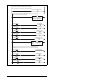
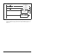
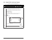
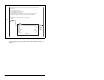
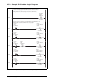
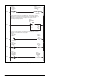
Figure 6.2 – Sample ControlLogix Ladder Logic Program
0
Local:3:O.CommandRegister.Run
Sample ControlLogix program with an MD65 drive at node address 1.
specifc tags for use elsewhere in the ladder program.
1
Copy File
Source Local:3:I.Data[0]
Dest DriveInputImage[0]
Length 2
COP
2
DriveInputImage[0].0
DriveStatusReady
3
DriveInputImage[0].1
DriveStatusActive
4
DriveInputImage[0].3
DriveStatusForward
5
DriveInputImage[0].7
DriveStatusFaulted
6
DriveInputImage[0].8
DriveStatusAtReference
7 Copy File
Source DriveInputImage[1]
Dest DriveFeedback
Length 1
COP
8
DriveCommandStop
DriveOutputImage[0].0
9
DriveCommandStart
DriveOutputImage[0].1
10
DriveCommandJog
DriveOutputImage[0].2
11
DriveCommandClearFaults
DriveOutputImage[0].3
Command bits and Reference) and writes them to the scanner for output over the network.
This rung enables the scanner (changes the scanner to RUN mode).
This section retrieves the Logic Status and Feedback data from the scanner and moves it to
This section takes the data from specific tags used elsewhere in the ladder program (Logic