
Manual


5-6
DeviceNet Communications Module
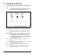
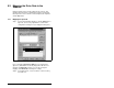
In our example, we are using a 1747-SDN and selected Discrete.
Step 3. In the Start Word box, select the word in memory at which
the data should start. In our example, we selected 1. Logic
Status and Speed Feedback information will be found in
I:1.1 and I:1.2, respectively.
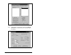
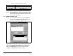
5.3.2 Mapping the Output I/O
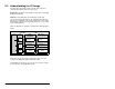
Step 1. In the Scanner Module dialog box, click the Output tab.
See figure 5.6. To display this dialog box, right-click the
scanner in the configuration view (figure 5.2).
If you selected the Automap on Add box in the Scanlist page
(figure 5.3), RSNetWorx has already mapped the I/O. If it is not
mapped, click Automap to map it. If you need to change the
mapping, click Advanced and change the settings.
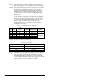
Table 5.3 – Scanner Module Memory Locations
Scanner Memory Locations
1747-SDN Discrete or M-File
1756-DNB Assembly Data
1771-SDN Block Xfer 62 – 57
Figure 5.6 – Output Page on the Scanner Module Dialog Box
01, MD65 A
C
Drive
01
,
MD65 w/MDCOMM-DNET
01
,
MD65 w/MDCOMM-DNET