
Manual

Installing the DeviceNet Module
3-5
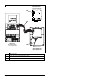
Step 6. Insert the DeviceNet cable plug into the mating module
receptacle and secure it with the two screws. (See figure
3.3, item 3.) Verify that the colors of the wires match up
with the color codes on the receptacle.
3.4 Connecting the Module to the Drive
Step 1. Remove power from the drive.
Step 2. Use static control precautions.
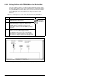
Step 3. Mount the module on the B- or C-Frame Communications
Module Cover using the screw on the DeviceNet module to
secure it into place. See figure 3.3. Also, refer to the
installation manual that shipped with the Communications
Cover (D2-3523).
• B-Frame Cover: M/N 6MD-COMMCVRB
• C-Frame Cover: M/N 6MD-COMMCVRC
Important: Tighten the screw in the lower left hole to ground the
module. See figure 3.4.
Step 4. Connect the Internal Interface cable to the MDI port on the
drive and then to the MDI connector on the module.
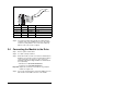
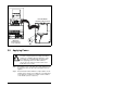
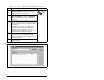
Terminal Color Signal Function
5 Red V+ Power Supply
4 White CAN_H Signal High
3 Bare SHIELD Shield
2 Blue CAN_L Signal Low
1BlackV– Common
Figure 3.2 – Connecting a 5-Pin Linear Plug to the Cable
5
4
3
2
1
Red
White
Bare
Blue
Black