
Manual


3-2
DeviceNet Communications Module
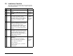
Important: If all switches are in the CLOSED position (all 0s), then
the Node Address and Data Rate are determined by
parameter settings in DN Addr Cfg (02) and DN Rate
Cfg (04).
Switches Description Default
SW 1 Least Significant Bit (LSB) of Node Address 1
Node 63
SW 2 Bit 1 of Node Address 1
SW 3 Bit 2 of Node Address 1
SW 4 Bit 3 of Node Address 1
SW 5 Bit 4 of Node Address 1
SW 6 Most Significant Bit (MSB) of Node Address 1
SW 7 Least Significant Bit (LSB) of Data Rate 1 Autobaud
SW 8 Most Significant Bit (MSB) of Data Rate 1
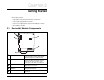
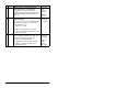
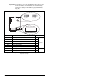
Figure 3.1 – Setting the Node Address/ Data Switches and Single-/Multi-Drive
Operation Jumper
J2
J2
Sin
g
le Drive
O
p
eratio
n
M
u
lti-Driv
e
O
p
eratio
n
2
1
8
3
4
5
6
7
N
O
D
E
RATE
U
P =
O
PEN =
1
2
1
8
3
4
5
6
7