
Manual


Getting Started
2-1
CHAPTER 2
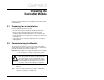
Getting Started
This chapter provides:
• A description of the DeviceNet module’s components
• A list of parts shipped with the module
• A list of user-supplied parts required for installing the module
• An installation checklist
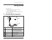
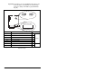
2.1 DeviceNet Module Components
Status Indicators
Three LEDs that indicate the status of the
connected drive, module, and network.
Refer to chapter 9, Troubleshooting.
MDI Connector A 20-pin, single-row shrouded male
header. An Internal Interface cable is
connected to this connector and a
connector on the drive. See table 2.2.
DeviceNet Connector A 5-pin connector to which a 5-pin linear
plug can be connected.
Node Address/Rate
Switches
Switches for setting the node address
and network data rate.
Mode Jumper (J2)
Selects Single- or Multi-Drive mode of
operation.
Figure 2.1 – Components of the DeviceNet Module
➊
➋
➌
➍
➎