DC3N DC Drive User Guide 1/4 to 2 HP, 115/230 VAC Instruction Manual D2-3451
The information in this manual is subject to change without notice. Throughout this manual, the following notes are used to alert you to safety considerations: m ATTENTION: Identifies information about practices or circumstances that can lead to personal injury or death, property damage, or economic loss. IMPORTANT: Identifies information that is critical for successful application and understanding of the product. m ATTENTION: The control circuit is at line potential when the drive is energized.
iii m Failure to observe these precautions could result in bodily injury. ATTENTION: This Drive contains ESD (Electric Static Discharge) sensitive parts and assemblies, Static control precautions are required when installing, testing, servicing, or repairing this assembly. Failure to observe these precautions could result in damage to, or destruction of, the equipment.
iv Contents Specifications 1 Dimensions 3 Installation 7 Chassis drive . . . . . . . . . . . . . . . . . . . . . . . . . . . . . . . . . . . . . . . . . . . . . .7 Mounting . . . . . . . . . . . . . . . . . . . . . . . . . . . . . . . . . . . . . . . . . . . . . . . .7 Isolation . . . . . . . . . . . . . . . . . . . . . . . . . . . . . . . . . . . . . . . . . . . . . . . .8 Heat sinking . . . . . . . . . . . . . . . . . . . . . . . . . . . . . . . . . . . . . . . . . . . . .9 Line fusing . . . . . . .
v Troubleshooting 35 Before troubleshooting . . . . . . . . . . . . . . . . . . . . . . . . . . . . . . . . . . . . . .35 Diagnostic LEDs . . . . . . . . . . . . . . . . . . . . . . . . . . . . . . . . . . . . . . . . . . .36 Functional Diagrams . . . . . . . . . . . . . . . . . . . . . . . . . . . . . . . . . . . . . . . .39 CE Compliance 41 External filtering . . . . . . . . . . . . . . . . . . . . . . . . . . . . . . . . . . . . . . . . . . .41 Line filters . . . . . . . . . . . . . . . . . . . . . . .
vi Illustrations Figure Figure Figure Figure Figure Figure Figure Figure Figure Figure Figure Figure Figure Figure Figure Figure Figure Figure Figure Figure Figure Figure Figure Figure Figure 1. DC3N-12D-00-010-AN Dimensions . . . . . . . . . . . . . . . . . . . . . . . .3 2. DC3N-12D-01-010-AN Dimensions . . . . . . . . . . . . . . . . . . . . . . . .4 3. DC3N-12D-4X-010-AN Dimensions . . . . . . . . . . . . . . . . . . . . . . . .5 4. Heat Sink Dimensions . . . . . . . . . . . . . . . . . . . . . . . .
vii Tables Table Table Table Table 1. 2. 3. 4. Recommended Line Fuse Sizes . . . . . . . . . . . . . . . . . . . . . . . . . .9 Recommended Dynamic Brake Resistor Sizes . . . . . . . . . . . . . . .23 Corcom® Filters . . . . . . . . . . . . . . . . . . . . . . . . . . . . . . . . . . . . . .41 Reliance Electric® Filters . . . . . . . . . . . . . . . . . . . . . . . . . . . . . . .
viii
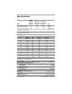
1 Specifications Max. Armature HP Range HP Range Current with 115 VAC with 230 VAC Model (Amps DC) Applied Applied Style DC3N-12D-00-010-AN† 10.0 1/8–1 1/4–2 Chassis DC3N-12D-01-010-AN‡ 10.0 1/8–1 1/4–2 NEMA 1 DC3N-12D-4X-010-AN‡‡ 10.0 1/8–1 1/4–2 NEMA12/4/4X † Double maximum armature current and horsepower when drive is mounted on heat sink part number DC3N-HS-00. ‡ Double maximum armature current and horsepower when drive is mounted on heat sink part number DC3N-HS-01.
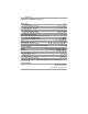
2 Specifications Adjustments and Application Data (cont.) Speed Range 60:1 Accel. Time Range 0–90 VDC Armature Voltage 0.5–17 seconds 0–180 VDC Armature Voltage 0.5–17 seconds Decel. Time Range 0-90 VDC Armature Voltage 0.5–17 seconds 0–180 VDC Armature Voltage 0.5–17 seconds Current Limit Overload Range 150% Analog Input Voltage Range (must be isolated; S1 to S2) for 0–90 VDC Armature Voltage 0–1.4 VDC for 0–180 VDC Armature Voltage 0–2.
3 Dimensions ALL DIMENSIONS IN INCHES [MILLIMETERS] Figure 1.
4 Dimensions TWO 0.88 [22] CONDUIT HOLES ALL DIMENSIONS IN INCHES [MILLIMETERS] Figure 2.
Dimensions FOUR MOUNTING SLOTS 0.19 INCHES [5 MILLIMETERS] WIDE TWO 0.88 [22] KNOCKOUTS ALL DIMENSIONS IN INCHES [MILLIMETERS] Figure 3.
6 Dimensions PART NO. DIM “A” DIM “B” DC3N-HS-00 4.40 [112] 3.00 [76] DC3N-HS-01 7.78 [198] 6.00 [152] Heat sinks sold separately. DIM “C” 0.7 [18] 0.89 [23] ALL DIMENSIONS IN INCHES [MILLIMETERS] Figure 4.
7 Installation m ATTENTION: Do not install, remove, or rewire this equipment with power applied. Doing so may cause fire or serious injury. Make sure you have read and understood the Attentions on page ii before attempting any of these procedures. • Protect the drive from dirt, moisture, and accidental contact. Provide sufficient room for access to the terminal block and calibration trimpots. • Mount the drive away from other heat sources.
8 Installation Shielding guidelines m ATTENTION: If it is not practical to shield power conductors, Reliance Electric recommends shielding all logic-level leads. If shielding is not practical, use twisted-pair control wiring to minimize induced electrical noise.
Installation 9 Observe the following guidelines when installing an isolation transformer: · A power disconnecting device must be installed between the power line and primary of the transformer. · If the power disconnecting device is a circuit breaker, the circuit breaker trip rating must be coordinated with the in-rush current (10-12 times full load current) of the transformer.
10 Installation Speed adjust potentiometer m ATTENTION: Because the reference potentiometer is connected through the regulator to the armature power circuit, its terminals are at line potential. Use a potentiometer that has a insulating shaft to insulate the operator knob from this power circuit and that is capable of withstanding Hi-pot tests at 2000 Volts DC for one minute. Failure to observe this precaution could result in severe bodily injury or loss of life.
Installation 11 Connections m ATTENTION: Do not connect this equipment with power applied. Failure to heed this directive may result in fire or serious injury. Power, fuse and motor connections Connect the power input leads, an external line fuse and a DC motor to the drive’s printed circuit board (PCB) as shown in Figure 6. Motor m ATTENTION: To provide the motor with overload protection, local, national, and international codes (e.g.
12 Installation NOTE: L1 IS THE HOT CONNECTION. L2 IS THE NEUTRAL CONNECTION. Figure 6.
Installation 13 Voltage follower m ATTENTION: The equipment is at line voltage when AC power is connected. Disconnect and lockout all ungrounded conductors of the AC power line. Failure to observe this precaution could result in severe bodily injury or loss of life. Instead of using a speed adjust potentiometer, the drive may be wired to follow an analog input voltage signal that is isolated from earth ground (Figure 7). Connect the signal input (+) to S2. Connect the signal common (–) to S1.
14 Installation Enclosed drive Mounting (NEMA 1 enclosure) The NEMA 1 enclosed drive comes with 0.88 inch (22 mm) conduit holes at the bottom of the enclosure. The units may be vertically wall mounted or horizontally bench mounted using the three keyholes on the back of the enclosure. 1. For access to the keyholes and the terminal strip, remove the two screws from the front of the enclosure by turning them counterclockwise. Grasp the front cover and lift it straight out. 2.
Installation 15 Heat sinking The DC3N Plate Style and NEMA1 enclosed models require additional heat sinking when the continuous armature current is above 5 ADC. Use Reliance Electric part numbers: • DC3N-HS-00 for the Plate Style drive • DC3N-HS-01 for the NEMA 1 enclosed drive NOTE: NEMA4X/12 models include a heatsink as standard. All other enclosed drives have sufficient heat sinking in their basic configurations.
16 Installation Power input m ATTENTION: Installation of a master power switch in the input line is required. This is the only way to disconnect power from the motor. The user is responsible for assuring safe conditions for operating personnel by providing suitable guards, audio or visual alarms, or other devices. Failure to observe these precautions could result in bodily injury.
17 Operation m ATTENTION: Change voltage switch settings only when the drive is disconnected from AC line voltage. Make sure both switches are set to their correct position. If the switches are improperly set to a lower voltage position, the motor will not run at full voltage and may cause damage to the transformer. If the switches are improperly set to a higher voltage position, the motor will overspeed, which may cause motor damage, or result in bodily injury or loss of life.
18 Operation Before applying power m ATTENTION: If the motor or drive does not perform as described, disconnect the AC line voltage immediately. Refer to the Troubleshooting section, page 35, for further assistance. • Set voltage switch SW501 and SW502 to either 115V or 230V to match the AC line voltage. Set voltage switch SW503 to either 90V or 180V to match the maximum armature voltage (Figure 9). • Verify that no conductive material is present on the printed circuit board.
Operation 19 DC3N Chassis Drives 1. Turn the speed adjust potentiometer full counterclockwise (CCW). 2. Apply AC line voltage. 3. Slowly advance the speed adjust potentiometer clockwise (CW). The motor slowly accelerates as the potentiometer is turned CW. Continue until the desired speed is reached. 4. Remove AC line voltage from the drive to coast the motor to a stop. DC3N Enclosed Drives (NEMA 1 and NEMA 4X) 1. Set the speed adjust potentiometer to “0” (full CCW). 2. Apply AC line voltage. 3.
20 Operation Starting and stopping using inhibit terminals m ATTENTION: Starting and stopping with the inhibit terminal pins does not disconnect AC power in the stop position. A hardwired AC power disconnection switch must be mounted in close proximity to the operator’s start/stop controls. This is required, as the DC3 drive does not have an armature loop contactor. A single fault like a power device short may cause motor rotation when in the stop mode.
Operation 21 Configuring the inhibit response m ATTENTION: The DC3 Drive is intended to operate at a predetermined minimum speed. If the application requires zero speed operation, the user is responsible for assuring safe conditions for operating personnel by providing suitable guards, audio or visual alarms, or other devices. Failure to observe these precautions could result in bodily injury.
22 Operation Decelerating to minimum speed m ATTENTION: The DC3 Drive is intended to operate at a predetermined minimum speed. If the application requires zero speed operation, the user is responsible for assuring safe conditions for operating personnel by providing suitable guards, audio or visual alarms, or other devices. Failure to observe these precautions could result in bodily injury. The switch shown in Figure 12 may be used to decelerate a motor to a minimum speed.
Operation 23 Dynamic braking m ATTENTION: Wait for the motor to completely stop before switching it back to RUN. This will prevent high armature currents from damaging the motor or drive. ATTENTION: Armature output can drift full ON with the switch in the BRAKE position and will be driven full ON if the minimum speed option is selected with the inhibit circuit. Failure to observe this precaution could result in severe bodily injury or loss of life.
24 Operation NOTE: SWITCH MUST BE RATED FOR AC LINE INPUT VOLTAGE Figure 13.
Operation Power supply header block The power supply header block can supply an unregulated +9 VDC (5 mA) to external devices when the motor and the power supply of the drive are fully loaded. More current is available with less motor loading. The power supply can supply an unregulated +15V (10 mA) signal in typical applications. POWER SUPPLY HEADER BLOCK Figure 14.
26 Calibration m ATTENTION: Dangerous voltages exist on the drive when it is powered, and up to 30 seconds after power is removed and the motor stops. When possible, disconnect the voltage input from the drive before adjusting the trimpots. If the trimpots must be adjusted with power applied, use insulated tools and the appropriate personal protection equipment. BE ALERT. High voltages can cause serious or fatal injury. ATTENTION: The control circuit is at line potential when the drive is energized.
Calibration 27 MIN SPD m ATTENTION: The DC3 Drive is intended to operate at a predetermined minimum speed. If the application requires zero speed operation, the user is responsible for assuring safe conditions for operating personnel by providing suitable guards, audio or visual alarms, or other devices. Failure to observe these precautions could result in bodily injury. The MIN SPD setting determines the motor speed when the speed adjust potentiometer is turned full CCW.
28 Calibration DECEL The DECEL setting determines the time the motor takes to ramp to a lower speed. See Specifications on page 1 for approximate deceleration times. DECEL is factory set for the fastest deceleration time (full CCW). To set the deceleration time: 1. Set the speed adjust potentiometer full CW. The motor should run at maximum speed. 2. Turn the speed adjust potentiometer full CCW and measure the time it takes the motor to go from maximum to minimum speed. 3.
Calibration 29 IR COMP The IR COMP trimpot setting determines the degree to which motor speed is held constant as the motor load changes. It is factory set for optimum motor regulation. To calibrate IR COMP (exact calibration): 1. Turn the IR COMP trimpot full CCW. 2. Set the speed adjust potentiometer until the motor runs at midspeed without load (for example, 900 RPM for an 1800 RPM motor) A hand held tachometer may be used to measure motor speed. 3.
30 Calibration Figure 16.
31 Application Notes Multiple fixed speeds Replace the speed adjust potentiometer with series resistors with a total series resistance of 5K ohm or 10K ohms (Figure 17). Add a single pole, multi-position switch with the correct number of positions for the desired number of fixed speeds. Figure 17.
32 Application Notes Independent adjustable speeds Replace the speed adjust potentiometer with a single pole, multi-position switch, and two or more potentiometers in parallel, with a total parallel resistance of 10K ohms. Figure 19 shows the connection of two independent speed adjust potentiometers that can be mounted at two separate operating stations. If desired, you can use two 5K ohm or 10K ohm potentiometers in parallel; however, the maximum speed adjust trimpot must then be recalibrated.
Application Notes 33 In the second wiring option, connect the RUN/JOG switch and the JOG pushbutton as shown in Figure 21. When the RUN/JOG switch is set to JOG, the motor decelerates to minimum speed (minimum speed is determined by the MIN SPD trimpot setting). Press the JOG pushbutton to jog the motor. Return the RUN/JOG switch to RUN for normal operation. Figure 20. RUN/JOG Switch Connection to Inhibit Plug Figure 21.
34 Application Notes Reversing m ATTENTION: At very low input levels, noise or drift could cause analog input polarity to change. This could cause the motor to rotate in the opposite direction. Proper precautions should be taken as this could result in damage to, or destruction of, the equipment. A dynamic brake may be used when reversing the motor direction (Figure 22). Use a three pole, three position switch rated for at least the maximum DC armature voltage and maximum braking current.
35 Troubleshooting m ATTENTION: This equipment is at line voltage when AC power is connected. Disconnect and lockout all ungrounded conductors of the AC power line before working on the unit. Failure to observe this precaution could result in severe bodily injury or loss of life. Before troubleshooting Perform the following steps before starting any procedure in this section: • Disconnect AC line voltage from the drive. • Check the drive closely for damaged components.
36 Troubleshooting Diagnostic LEDs The DC3N chassis drive is equipped with two diagnostic LEDs. Refer to Figure 23 for LED location. Power (PWR): Lights whenever the AC line voltage is applied to the drive. Current Limit (CURR LIMIT or CL): Lights whenever the drive reaches current limit. POWER TQ LIMIT Figure 23.
Troubleshooting 37 Problem Possible Causes Suggested Solutions Line fuse blows. 1. Line fuse is the wrong size. 1. Check that the line fuse is correct for the motor size. 2. Motor cable or armature is shorted to ground. 2. Check motor cable and armature for shorts. 3. Nuisance tripping caused by a combination of ambient conditions and highcurrent spikes (i.e. reversing). 3.
38 Troubleshooting Problem Possible Causes Suggested Solutions Motor does not stop when the speed adjust potentiometer is full CCW. MIN SPD setting is too high. Calibrate MIN SPD. Motor runs in the opposite direction (nonreversing drives). Motor connections to A1 and A2 are reversed. Reverse connections to A1 and A2. Motor runs too fast. 1. MAX SPD and MIN SPD are set too high. 1. Calibrate MAX SPD and MIN SPD. Motor will not reach the desired speed. 1. MAX SPD setting is too low. 1.
Functional Diagrams Troubleshooting 39 Figure 24.
40 Troubleshooting Figure 25.
41 CE Compliance Reliance Electric Corporation hereby certifies that its DC3N series drives have been approved to bear the “CE” mark provided the conditions of approval have been met by the end user. The DC3N series has been tested to the following test specifications: EN55011:1991 (emissions), and EN50082-1:1992 (immunity) Compliance allows Reliance Electric’s DC3N series to bear the CE mark. The end user, as described herein, falls into one of two categories: 1.
42 CE Compliance Armature filters If the end-user is not using a CE-approved motor, a second filter on the armature must be deployed. This filter will have the Reliance Electric part number CEXXMM, where XX is the motor current rating listed on the nameplate. Reliance Electric® Filters are listed below. Table 4. Reliance Electric® Filters Nameplate Current of Motor Wired to the Drive 0 to 4 amps 4.
U.S. Drives Technical Support Tel: (1) 262.512.8176, Fax: (1) 262.512.2222, Email: support@drives.ra.rockwell.com, Online: www.ab.com/support/abdrives Publication D2-3451- December 1999 Copyright © 1999 Rockwell Automation, Inc. All Rights Reserved. Printed in USA.