250-0287-rev2.
50-0287-rev2.qxd 3/12/01 10:27 AM Page b The information in this manual is subject to change without notice. Throughout this manual, the following notes are used to alert you to safety considerations: ATTENTION: Identifies information about practices or circumstances that can lead to personal injury or death, property damage, or economic loss. IMPORTANT: Identifies information that is critical for successful application and understanding of the product.
250-0287-rev2.qxd 3/12/01 10:27 AM Page i i ATTENTION: Only qualified personnel familiar with the construction and operation of this equipment and the hazards involved should install, adjust, operate, and/or service this equipment. Read and understand this instruction manual in its entirety before proceeding. Failure to observe this precaution could result in severe bodily injury or loss of life. ATTENTION: The user is responsible for conforming with all applicable local and national codes.
250-0287-rev2.qxd ii 3/12/01 10:27 AM Page ii Safety Warnings ATTENTION: Starting and stopping with the start/stop terminals does not disconnect AC power in the stop position. A hardwired AC power disconnection switch must be mounted between the AC source and terminals L I and L2. This is required, as the DC drive does not have an armature loop contactor. A single fault like a power device short may cause motor rotation when in the stop mode.
250-0287-rev2.qxd 3/12/01 10:27 AM Page iii iii Contents Specifications 1 Dimensions and Layout 4 Installation 7 Wiring . . . . . . . . . . . . . . . . . . . . . . . . . . . . . . . . . . . . . . . . . . . . . . .8 Shielding guidelines . . . . . . . . . . . . . . . . . . . . . . . . . . . . . . . . . .8 Chassis drive . . . . . . . . . . . . . . . . . . . . . . . . . . . . . . . . . . . . . . . .10 Mounting . . . . . . . . . . . . . . . . . . . . . . . . . . . . . . . . . . . . . . . . . .
250-0287-rev2.qxd iv 3/12/01 10:27 AM Page iv Table of Contents Field output . . . . . . . . . . . . . . . . . . . . Tachometer feedback . . . . . . . . . . . . . Voltage or current follower . . . . . . . . . Slide switches . . . . . . . . . . . . . . . . . . . . . . LINE VOLTAGE (SW501 and SW502) . . MOTOR (SW503) . . . . . . . . . . . . . . . . . SIGNAL (SW504) . . . . . . . . . . . . . . . . . FEEDBACK (SW505) . . . . . . . . . . . . . . . Operation Before applying power (all models) . . . . . . .
250-0287-rev2.qxd 3/12/01 10:27 AM Page v Table of Contents DECEL . . . . . . . . . . . . . . . . . . . . . . . . . . . . . TACH VOLTS . . . . . . . . . . . . . . . . . . . . . . . . . Application Notes Multiple fixed speeds . . . . . . . . . . . . . . . . . . . . . Adjustable speeds using potentiometers in series Independent adjustable speeds . . . . . . . . . . . . . Reversing . . . . . . . . . . . . . . . . . . . . . . . . . . . . . RUN/JOG switch . . . . . . . . . . . . . . . . . . . . . . . .
250-0287-rev2.qxd 3/12/01 10:27 AM Page vi vi Illustrations Figure Figure Figure Figure Figure Figure Figure Figure Figure Figure Figure Figure Figure Figure Figure Figure Figure Figure 1. 2. 3. 4. 5. 6. 7. 8. 9. 10. 11. 12. 13. 14. 15. 16. 17. 18. Figure 19. Figure 20. DC3N-12D-00-010-AI Dimensions . . . . . . . . . . . . . . . . . .4 DC3N-12D-4X-010-AI Dimensions . . . . . . . . . . . . . . . . . .5 PC Board Layout . . . . . . . . . . . . . . . . . . . . . . . . . . . . . . .
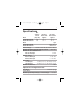
250-0287-rev2.qxd 3/12/01 10:27 AM Page 1 1 Specifications Model DC3N-12D-00-010-AI DC3N-12D-4X-010-AI Max.
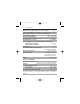
250-0287-rev2.qxd 2 3/12/01 10:27 AM Page 2 Specifications Minimum Speed Trimpot Range (% of rated voltage) 0 to 50% Torque Trimpot Maximum Setting (% of maximum current) 200% IR Drop Compensation (% of rated armature voltage) 0 to 15% Acceleration Time Range 0.5 – 10 seconds Deceleration Time Range 0.
250-0287-rev2.qxd 3/12/01 10:27 AM Page 3 Specifications 3 Drive Ratings DC Motor Motor Rated DC Armature Field Field Motor AC Line Input Armature Current Voltage Current HP Amps KVA Voltage (Amps) (Amps) 1/4 4.5 0.5 90 2.7 50 1 4.5 0.5 90 2.7 100 1 1/3 5.9 0.7 90 3.5 50 1 5.9 0.7 90 3.5 100 1 1/2 7.8 0.9 90 5 50 1 3.7 0.8 180 2.5 100 1 3.7 0.8 180 2.5 200 1 3/4 10.6 1.2 90 7.6 50 1 5.6 1.3 180 3.8 100 1 5.6 1.3 180 3.8 200 1 1 13 1.5 90 10 50 1 7 1.6 180 5 100 1 7 1.6 180 5 200 1 1.5 ------10.1 2.
250-0287-rev2.qxd 3/12/01 10:27 AM Page 4 4 Dimensions and Layout Figure 1.
250-0287-rev2.qxd 3/12/01 10:27 AM Page 5 Dimensions THREE 0.88 [22] KNOCKOUTS ALL DIMENSIONS IN INCHES [MILLIMETERS] Figure 2.
250-0287-rev2.qxd 6 3/12/01 10:27 AM Page 6 Dimensions and Layout Figure 3.
250-0287-rev2.qxd 3/12/01 10:27 AM Page 7 7 Installation Only qualified technical personnel, ATTENTION: familiar with the construction and operation of this equipment and the hazards involved, should install, adjust, operate and/or service this equipment. Read and understand this instruction manual in its entirety before proceeding. Failure to observe this precaution could result in severe bodily injury or loss of life. ATTENTION: This equipment is at line voltage when AC power is connected.
250-0287-rev2.qxd 8 3/12/01 10:27 AM Page 8 Installation Wiring Circuit potentials are at 115 or 230 ATTENTION: VAC above ground. To prevent the risk of injury or fatality, avoid direct contact with the printed circuit board or with circuit elements. Use a non-metallic screwdriver for the calibration trimpots. ATTENTION: Do not disconnect any of the motor leads from the drive unless power is removed or the drive is disabled. Opening any one motor lead may destroy the drive.
250-0287-rev2.qxd 3/12/01 10:27 AM Page 9 Installation 9 Under no circumstances should power ATTENTION: and logic leads be bundled together. Induced voltage can cause unpredictable behavior any electronic device, including motor controls.
250-0287-rev2.qxd 10 3/12/01 10:27 AM Page 10 Installation Chassis drive This drive contains ESD (Electric Static ATTENTION: Discharge) sensitive parts and assemblies. Static control precautions are required when installing, testing, servicing, or repairing this assembly. Failure to observe these precautions could result in damage to, or destruction of, the equipment. Mounting Protect the drive from dirt, moisture, and accidental contact.
250-0287-rev2.qxd 3/12/01 10:27 AM Page 11 Installation 11 The chassis units do not have to be earth grounded. If you choose to ground the chassis, use a star washer beneath the head of at least one of the mounting screws to penetrate the anodized chassis surface and to reach bare metal.
250-0287-rev2.qxd 12 3/12/01 10:27 AM Page 12 Installation Observe the following guidelines when installing an isolation transformer: · A power disconnecting device must be installed between the power line and primary of the transformer. · If the power disconnecting device is a circuit breaker, the circuit breaker trip rating must be coordinated with the in-rush current (10-12 times full load current) of the transformer.
250-0287-rev2.qxd 3/12/01 10:27 AM Page 13 Installation 13 Line fusing This DC3 drive model has 15-amp line fuses preinstalled on fuse holders 501 and 502 (FU501 and FU502). When replacing the line fuses, use fast acting fuses rated for 250 VAC or higher. See Figure 3, page 6, for fuse holder location, and Table 1 for recommended replacement line fuse sizes for specific application ratings. Table 1. Recommended Line Fuse Sizes 90 VDC Motor Horsepower 180 VDC Motor Max.
250-0287-rev2.qxd 14 3/12/01 10:27 AM Page 14 Installation Speed adjust potentiometer Install the circular insulating disk between the mounting panel and the 10K ohm speed adjust potentiometer (see Figure 4). Mount the speed adjust potentiometer through a 0.38 inch (10 mm) hole with the hardware provided. Twist the speed adjust potentiometer wire to avoid picking up unwanted electrical noise. If potentiometer leads are longer than 18 inches (46 cm), use shielded cable. Figure 4.
250-0287-rev2.qxd 3/12/01 10:27 AM Page 15 Installation 15 Alternate speed adjust potentiometer connections Alternate speed adjust potentiometer connections may be found in the Application Notes section of this user guide. IMPORTANT: The user may choose to install a 5K ohm speed adjust potentiometer; however, the MIN SPD and MAX SPD trimpots must be recalibrated if the 5K ohm potentiometer is used.
250-0287-rev2.qxd 16 3/12/01 10:27 AM Page 16 Installation Cage-clamp terminals Logic connections are made to cage-clamp terminals. To insert a wire into the cage-clamp terminal: 1. Press down on the lever arm using a small screwdriver. 2. Insert wire into the wire clamp. 3. Release the lever arm to clamp wire. Figure 5.
0-0287-rev2.qxd 3/12/01 10:27 AM Page 17 Installation 17 Connections Do not connect this equipment with ATTENTION: power applied. Failure to follow this directive may result in fire or serious injury. ATTENTION: Starting and stopping with the start/stop terminals does not disconnect AC power in the stop position. A hardwired AC power disconnection switch must be mounted between the AC source and terminals L I and L2. This is required, as the DC3 drive does not have an armature loop contactor.
250-0287-rev2.qxd 18 3/12/01 10:27 AM Page 18 Installation Installation of a master power switch in ATTENTION: the input line is required. This is the only way to disconnect power from the motor. The user is responsible for assuring safe conditions for operating personnel by providing suitable guards, audio or visual alarms, or other devices. Failure to observe these precautions could result in bodily injury.
250-0287-rev2.qxd 3/12/01 10:27 AM Page 19 Installation 19 Connect a motor to terminals A1 and A2 as shown in Figure 6 (page 23). Ensure that the motor voltage rating is consistent with the drive’s output voltage. Power input Installation of a master power switch in ATTENTION: the input line is required. This is the only way to disconnect power from the motor.
250-0287-rev2.qxd 20 3/12/01 10:27 AM Page 20 Installation Field output Do not make any connections to F1 and ATTENTION: F2 when using a permanent magnet motor. The field output is for shunt wound motors only. See Table 2 for field output connections. Table 2.
250-0287-rev2.qxd 3/12/01 10:27 AM Page 21 Installation 21 START/STOP pushbuttons Starting and stopping with the start/stop ATTENTION: terminals does not disconnect AC power in the stop position. A hardwired AC power disconnection switch must be mounted between the AC source and terminals L I and L2. This is required, as the DC3 drive does not have an armature loop contactor. A single fault like a power device short may cause motor rotation when in the stop mode.
250-0287-rev2.qxd 22 3/12/01 10:27 AM Page 22 Installation Tachometer feedback Applying the incorrect polarity to the ATTENTION: tachometer can cause an overspeed condition. Make sure the positive (+) wire is connected to terminal T1 and the negative (-) wire is connect to terminal T2 when the motor is running in the forward direction. Failure to observe this precaution could result in bodily injury.
250-0287-rev2.qxd 3/12/01 10:27 AM Page 23 Installation NOTES 1. L1 IS THE HOT TERMINAL. 2. L2/115 IS THE NEUTRAL TERMINAL FOR 115 VAC INPUT. 3. L2/230 IS THE NEUTRAL TERMINAL FOR 230 VAC INPUT. 4. TYPICAL FIELD CONNECTIONS SHOWN. REFER TO TABLE 2 (PAGE 29) FOR ALTERNATE FIELD CONNECTIONS. Figure 6.
250-0287-rev2.qxd 24 3/12/01 10:27 AM Page 24 Installation Voltage or current follower Instead of using a speed adjust potentiometer, these DC3N model drives may be wired to follow an external input signal (see Figure 7 for connections). This input signal can be in the form of voltage (0-10 VDC) or current (4-20 mA). Because these drives have built in isolation the input signal can be either grounded or ungrounded.
250-0287-rev2.qxd 3/12/01 10:27 AM Page 25 Installation 25 Enclosed drive Mounting The NEMA 4X enclosed drive comes with 0.88 inch (22 mm) conduit knockout holes at the bottom of the enclosure. The units may be vertically wall mounted using the four 0.19 inch (5 mm) slotted holes on the attached heat sink. For motor loads less than 5 ADC, the drive may be bench mounted horizontally, or operated without mounting. Mount the drive as follows: 1. Install the mounting screws. 2.
250-0287-rev2.qxd 26 3/12/01 10:27 AM Page 26 Installation 6. Turn the slotted screw clockwise until tight to secure the front cover. 7. Set the POWER switch to the OFF position before applying the AC line voltage. Heat sinking The enclosed DC3N drive contains sufficient heat sinking in its basic configuration. No additional heat sinking is necessary when installed in accordance with the guidelines specified in this manual.
250-0287-rev2.qxd 3/12/01 10:27 AM Page 27 Installation 27 Connections A single fault like a power device short ATTENTION: may cause motor rotation when in the stop mode. The user is responsible for assuring safe conditions for operating personnel by providing suitable guards, audio or visual alarms, or other devices. Failure to observe these precautions could result in bodily injury. ATTENTION: To provide the motor with overload protection, local, national, and international codes (e.g.
250-0287-rev2.qxd 28 3/12/01 10:27 AM Page 28 Installation Motor To provide the motor with overload ATTENTION: protection, local, national, and international codes (e.g., NEC/CEC) require that a motor thermostat, internal to the motor, be installed or an electronic thermal motor overload relay, sized to protect the motor, be installed between the motor and the drives output terminals. IMPORTANT: Reliance Electric drives supply motor voltage from A1and A2 terminals.
250-0287-rev2.qxd 3/12/01 10:27 AM Page 29 Installation 29 Power input Connect the AC line power leads to terminals L1 and L2 as shown in Figure 8 (page 31). Ensure that earth ground is connected to the green screw inside the case. Field output Do not make any connections to F1 and ATTENTION: F2 when using a permanent magnet motor.The field output is for shunt wound motors only. See Table 3 for field output connections. Table 3.
250-0287-rev2.qxd 30 3/12/01 10:27 AM Page 30 Installation Tachometer feedback Applying the incorrect polarity to the ATTENTION: tachometer can cause an overspeed condition. Make sure the positive (+) wire is connected to terminal T1 and the negative (-) wire is connect to terminal T2 when the motor is running in the forward direction. Failure to observe this precaution could result in bodily injury.
250-0287-rev2.qxd 3/12/01 10:27 AM Page 31 Installation SEE NOTES 1, 2 AND 3 SEE NOTE 4 NOTES 1. L1 IS THE HOT TERMINAL. 2. L2/115 IS THE NEUTRAL TERMINAL FOR 115 VAC INPUT. 3. L2/230 IS THE NEUTRAL TERMINAL FOR 230 VAC INPUT. 4. TYPICAL FIELD CONNECTIONS SHOWN. REFER TO TABLE 2 (PAGE 29) FOR ALTERNATE FIELD CONNECTIONS. Figure 8.
250-0287-rev2.qxd 32 3/12/01 10:27 AM Page 32 Installation Voltage or current follower Instead of using a speed adjust potentiometer, these DC3N series drives may be wired to follow an external input signal (see Figure 8 on page 31 for connections). This input signal can be in the form of voltage (0-10 VDC) or current (4-20 mA). Because these drives have built-in isolation, the input signal can be either grounded or ungrounded.
250-0287-rev2.qxd 3/12/01 10:27 AM Page 33 Installation 33 Slide switches Change slide switch settings only when ATTENTION: the drive is disconnected from the AC line voltage. Make sure both line voltage and motor switches are set to their correct position. If the switches are improperly set to a lower voltage position, the motor will not run at full voltage and may cause transformer damage.
250-0287-rev2.qxd 34 3/12/01 10:27 AM Page 34 Installation SIGNAL (SW504) Select the input signal being used: CURR for 4-20 mADC current input signal, or VOLT for 0-10 VDC voltage input signal or speed adjust potentiometer input. FEEDBACK (SW505) The DC3N does not have tachometer ATTENTION: loss or a field loss protection. Loss of field or tachometer will cause the motor to run at maximum uncontrolled speed.
250-0287-rev2.qxd 3/12/01 10:27 AM Page 35 Installation Figure 9.
250-0287-rev2.qxd 3/12/01 10:27 AM Page 36 36 Operation Change voltage switch settings only ATTENTION: when the drive is disconnected from AC line voltage. Make sure both switches are set to their correct position. If the switches are improperly set to a lower voltage position, the motor will not run at full voltage and may cause damage to the transformer.
250-0287-rev2.qxd 3/12/01 10:27 AM Page 37 Operation 37 Before applying power (all models) If the motor or drive does not perform ATTENTION: as described, disconnect the AC line voltage immediately. Refer to the Troubleshooting section, page 67, for further assistance. • Set LINE VOLTAGE SELECT switches SW501 and SW502 to either 115V or 230V to match the AC line voltage. • Set ARMATURE VOLTAGE SELECT switch SW503 to either 90V or 180V to match the maximum armature voltage.
250-0287-rev2.qxd 38 3/12/01 10:27 AM Page 38 Operation Drive operation Chassis drive operation POWER ON start SPEED REFERENCE: External signal or potentiometer START/STOP control: POWER ON/OFF IMPORTANT: It is necessary to wire a jumper between B1 and B3 if no START/STOP switches are to be used. IMPORTANT: Line starting and line stopping (applying and removing AC line voltage) is recommended for infrequent starting and stopping of a drive only.
250-0287-rev2.qxd 3/12/01 10:27 AM Page 39 Operation 3. 4. 39 Slowly increase the speed reference signal. The motor slowly accelerates as the potentiometer is turned CW or the external speed reference is increased. Continue until the desired speed is reached. Remove AC line voltage to coast the motor to a stop.
250-0287-rev2.qxd 40 3/12/01 10:27 AM Page 40 Operation 2. Apply AC line voltage. 3. Slowly increase the speed reference signal and press the START pushbutton. The motor accelerates as the potentiometer is turned CW or the external speed reference is increased. Continue until the desired speed is reached. 4. Press STOP pushbutton to coast motor to a stop.
250-0287-rev2.qxd 3/12/01 10:27 AM Page 41 Operation 41 Alternate Starting and Stopping Methods The DC3 Drive is intended to operate ATTENTION: at a predetermined minimum speed. If the application requires zero speed operation, the user is responsible for assuring safe conditions for operating personnel by providing suitable guards, audio or visual alarms, or other devices. Failure to observe these precautions could result in bodily injury.
250-0287-rev2.qxd 42 3/12/01 10:27 AM Page 42 Operation Minimum speed The circuit shown in Figure 10 may be used to decelerate a motor to a minimum speed. Closing the switch between S1 and S2 decelerates the motor from set speed to a minimum speed determined by the MIN SPD trimpot setting. If the MIN SPD trimpot is set full CCW, the motor decelerates to zero speed when the switch between S1 and S2 is closed. The DECEL trimpot setting determines the rate at which the drive decelerates.
250-0287-rev2.qxd 3/12/01 10:27 AM Page 43 Operation 43 Dynamic braking Wait for the motor to completely stop ATTENTION: before switching it back to RUN. This will prevent high armature currents from damaging the motor. ATTENTION: Armature output can drift full ON with the switch in the BRAKE position and will be driven full ON if the minimum speed option is selected with the inhibit circuit. Failure to observe this precaution could result in severe bodily injury or loss of life.
250-0287-rev2.qxd 44 3/12/01 10:27 AM Page 44 Operation Table 4. Minimum Recommended Dynamic Brake Resistor Values Motor Armature Current Rating Wattage Less than 2 ADC 2–3 ADC 3–5 ADC 5–10 ADC Minimum Dynamic Brake Resistor Value 1 ohm 5 ohm 10 ohm 20 ohm Minimum Dynamic Brake Resistor 1W 5W 20W 40W DC3N DRIVE Figure 11.
250-0287-rev2.qxd 3/12/01 10:27 AM Page 45 Operation 45 Enclosed drive operating modes If you run the drive in AUTO mode, you ATTENTION: must recalibrate the MIN SPD trimpot to offset any motor drift caused by the input signal. Refer to the Calibration section (page 48) for more information. The mode selector switch on the drive, mounted on its cover, provides the option of operating in either MANUAL (mounted speed potentiometer) or AUTO (external signal source) mode.
250-0287-rev2.qxd 46 3/12/01 10:27 AM Page 46 Operation Auto mode IMPORTANT: If you run the drive in AUTO mode using an external current signal, you must recalibrate the MIN SPD trimpot to offset any motor drift caused by the input signal. IMPORTANT: When switching between MANUAL and AUTO (0-10 VDC) modes, you must balance the MIN SPD trimpot setting for both operating modes. Set the mode selector switch to AUTO if you wish to follow an external signal, independent of the speed adjust knob setting.
250-0287-rev2.qxd 3/12/01 10:27 AM Page 47 Operation 47 Frequent starting and stopping can ATTENTION: produce high torque. This may cause damage to motors, especially gearmotors that are not properly sized for the application. To 1. 2. 3. 4. run the motor: Set the speed adjust potentiometer to “0” (full CCW). Apply AC line voltage. Set the POWER switch to the ON position. Slowly advance the speed adjust potentiometer clockwise (CW), or increase the external reference signal.
250-0287-rev2.qxd 3/12/01 10:27 AM Page 48 48 Calibration Dangerous voltages exist on the drive ATTENTION: when it is powered, and up to 30 seconds after power is removed and the motor stops. When possible, disconnect the voltage input from the drive before adjusting the trimpots. If the trimpots must be adjusted with power applied, use insulated tools and the appropriate personal protection equipment. BE ALERT. High voltages can cause serious or fatal injury.
250-0287-rev2.qxd 3/12/01 10:27 AM Page 49 Calibration IR COMP DECELERATION CURRENT LIMIT ACCELERATION 49 TACH VOLTS MAXIMUM SPEED Figure 12.
250-0287-rev2.qxd 50 3/12/01 10:27 AM Page 50 Calibration Drive Calibration Procedure Prepare the DC3N drive for calibration as follows. This procedure applies to both chassis and enclosed drives. 1. 2. 3. 4. 5. 6. Ensure that no power is applied to the drive. If you use an enclosed drive, you must open the drive cover to gain access to the trimpots. Turn the slotted screw on the front cover counterclockwise until it is free from the enclosure.
250-0287-rev2.qxd 3/12/01 10:27 AM Page 51 Calibration 51 MIN SPD The DC3N Drive is intended to operate ATTENTION: at a predetermined minimum speed. If the application requires zero speed operation, the user is responsible for assuring safe conditions for operating personnel by providing suitable guards, audio or visual alarms, or other devices. Failure to observe these precautions could result in bodily injury.
250-0287-rev2.qxd 52 3/12/01 10:27 AM Page 52 Calibration MAX SPD The MAX SPD setting determines the motor speed when the speed adjust potentiometer or external reference signal is set for maximum speed. It is factory set for maximum rated motor speed. To calibrate MAX SPD: 1. Set the MAX SPD trimpot full CCW. 2. Turn the speed adjust potentiometer full CW or set the external reference signal for maximum speed. 3. Adjust the MAX SPD trimpot until the desired maximum motor speed is reached.
250-0287-rev2.qxd 3/12/01 10:27 AM Page 53 Calibration 53 CURRENT LIMIT Although the CURRENT LIMIT ATTENTION: trimpot is set to 120% of the maximum drive current rating, continuous operation at that rating may damage the drive or motor. The CURRENT LIMIT setting determines the maximum armature current output of the drive. It is factory set at 120% of maximum drive current. If you use a lower horsepower motor, CURRENT LIMIT must be recalibrated for the motor.
250-0287-rev2.qxd 54 3/12/01 10:27 AM Page 54 Calibration 6. Adjust the CURRENT LIMIT trimpot slowly CW until the armature current is 120% of motor rated current. 7. Set the speed adjust potentiometer or external reference signal for zero speed and remove power. 8. Remove the lock on the motor armature shaft. IR COMP The IR COMP setting determines the degree to which motor speed is held constant as the motor load changes. It is factory set at optimum motor regulation for the highest motor horsepower.
250-0287-rev2.qxd 3/12/01 10:27 AM Page 55 Calibration 55 Approximate IR COMP calibration: If the motor does not maintain set speed as the load changes, gradually rotate the IR COMP trimpot CW. If the motor oscillates (overcompensation), the IR COMP trimpot may be set too high (CW). Turn the IR COMP trimpot CCW to stabilize the motor speed. ACCEL The ACCEL setting determines the time the motor takes to ramp to a higher speed, within the limits of available torque.
250-0287-rev2.qxd 56 3/12/01 10:27 AM Page 56 Calibration DECEL The DECEL setting determines the time the motor takes to ramp to lower speed, within the limits of available torque. The DECEL setting is factory set for its fastest deceleration time (full CCW). To calibrate DECEL: 1. Set the speed adjust potentiometer or external reference signal for maximum speed. The motor should run at maximum speed. 2.
250-0287-rev2.qxd 3/12/01 10:27 AM Page 57 Calibration 57 TACH VOLTS Applying the incorrect polarity to the ATTENTION: tachometer can cause an overspeed condition. Make sure the positive (+) wire is connected to terminal T1 and the negative (-) wire is connect to terminal T2 when the motor is running in the forward direction. Failure to observe this precaution could result in bodily injury. ATTENTION: The control circuit is at line potential when the drive is energized.
250-0287-rev2.qxd 58 3/12/01 10:27 AM Page 58 Calibration 3. Set switch 505 (SW505) to ARM for armature feedback. 4. Apply power to drive. 5. Set the speed adjust potentiometer or external reference signal to maximum speed. 6. Measure the armature voltage across A1 and A2 using a voltmeter. 7. Disconnect power from drive. 8. Set the speed adjust potentiometer or external reference signal to minimum speed. 9. Set SW505 to TACH for tachometer feedback. 10. Set the IR COMP trimpot full CCW. 11.
250-0287-rev2.qxd 3/12/01 10:27 AM Page 59 Calibration Figure 13.
250-0287-rev2.qxd 3/12/01 10:27 AM Page 60 60 Application Notes The equipment is at line voltage when ATTENTION: AC power is connected. Disconnect and lockout all ungrounded conductors of the AC power line. Failure to observe this precaution could result in severe bodily injury or loss of life. This section shows typical chassis drive connections. Multiple fixed speeds Replace the speed adjust potentiometer with series resistors with a total series resistance of 10K ohms (Figure 14).
250-0287-rev2.qxd 3/12/01 10:27 AM Page 61 Application Notes 61 Adjustable speeds using potentiometers in series Replace the speed adjust potentiometer with a single pole, multi-position switch, and two or more potentiometers in series, with a total series resistance of 10K ohms. Figure 15 shows a connection for fixed high and low speed adjust potentiometers. Figure 15.
250-0287-rev2.qxd 62 3/12/01 10:27 AM Page 62 Application Notes Independent adjustable speeds Replace the speed adjust potentiometer with a single pole, multi-position switch, and two or more potentiometers in parallel, with a total parallel resistance of 10K ohms. Figure 16 shows the connection of two independent speed adjust potentiometers that can be mounted at two separate operating stations. Figure 16.
250-0287-rev2.qxd 3/12/01 10:27 AM Page 63 Application Notes 63 Reversing The DC3 Drive is intended to operate ATTENTION: at a predetermined minimum speed. If the application requires zero speed operation, the user is responsible for assuring safe conditions for operating personnel by providing suitable guards, audio or visual alarms, or other devices. Failure to observe these precautions could result in bodily injury.
250-0287-rev2.qxd 64 3/12/01 10:27 AM Page 64 Application Notes Figure 17.
250-0287-rev2.qxd 3/12/01 10:27 AM Page 65 Application Notes 65 RUN/JOG switch Starting and stopping with the start/stop ATTENTION: terminals does not disconnect AC power in the stop position. A hardwired AC power disconnection switch must be mounted between the AC source and terminals L I and L2. This is required, as the DC3 drive does not have an armature loop contactor. A single fault like a power device short may cause motor rotation when in the stop mode.
250-0287-rev2.qxd 66 3/12/01 10:27 AM Page 66 Application Notes Figure 18.
250-0287-rev2.qxd 3/12/01 10:27 AM Page 67 67 Troubleshooting This equipment is at line voltage when ATTENTION: AC power is connected. Disconnect and lockout all ungrounded conductors of the AC power line before working on the unit. Failure to observe this precaution could result in severe bodily injury or loss of life. Before troubleshooting Perform the following steps before starting any procedure in this section: • • • • • • • • Disconnect AC line voltage from the drive.
250-0287-rev2.qxd 68 3/12/01 10:27 AM Page 68 Troubleshooting Diagnostic LEDs DC3N Series drives are equipped with two diagnostic LEDs (see Figure 19 for LED location). The red CURRENT LIMIT LED turns on whenever the drives reaches current limit and stays off whenever the drive is not in current limit (normal operation). The green POWER LED turns on whenever AC line voltage is applied to the drive and stays off whenever there is no AC line voltage applied to the drive. POWER CURRENT LIMIT Figure 19.
250-0287-rev2.qxd 3/12/01 10:27 AM Page 69 Troubleshooting Problem Line fuse blows Possible Causes 69 Suggested Solutions 1. Line fuses are the wrong size. 1. Check that line fuses are correct for motor size (page 13). 2. Motor cable or armature is shorted to ground. 2. Check motor cable and armature for shorts. 3. Nuisance tripping caused by a combination of ambient conditions and high-current spikes (i.e. reversing). 3.
250-0287-rev2.qxd 70 3/12/01 10:27 AM Page 70 Troubleshooting Problem Line fuse does not blow, but motor does not run Possible Causes Suggested Solutions 1. Speed adjust potentiometer, voltage external reference signal, or current external reference signal set to zero speed. 1. Increase the speed adjust potentiometer, voltage, or current setting. 2. Speed adjust potentiometer, voltage or current external reference signal not connected to drive input properly; connections are open. 2.
250-0287-rev2.qxd 3/12/01 10:27 AM Page 71 Troubleshooting Problem Line fuse does not blow, but motor does not run (cont.) Possible Causes Suggested Solutions 5. Drive is not receiving AC line voltage. 5. Apply AC line voltage to L1 and L2. 6. Motor is not connected. 6. Connect motor to A1 and A2. 7. B1 not connected to B3 (if START/STOP pushbuttons are not used). 7. Connect B1 to B3. 8. Motor is stalled because of incorrect field connections (shunt wound motors only). 8.
250-0287-rev2.qxd 72 3/12/01 10:27 AM Page 72 Troubleshooting Problem Possible Causes Suggested Solutions Motor runs too fast at set speed 1. MIN SPD and MAX SPD settings are too high. 1. Recalibrate MIN SPD and MAX SPD. 2. Motor field connections are loose (shunt wound motors only). 2. Check motor field connections. 3. Motor is demagnetized. 3. Check for proper braking technique and method by which power is cycled. 4. Tachometer leads are reversed. 4. Check tachometer connections.
250-0287-rev2.qxd 3/12/01 10:27 AM Page 73 Troubleshooting Problem Motor runs too slow or too fast Possible Causes 73 Suggested Solutions 1. Switches are set incorrectly. 1. Verify all switch settings. 2. MIN SPD and MAX SPD not calibrated. 2. Calibrate MIN SPD and MAX SPD. 3. Motor field not properly connected (shunt wound motors only). 3. Verify motor field connections. 4. TACH VOLTS trimpot not calibrated properly. 4. Recalibrate TACH VOLTS trimpot. 5. Motor is demagnetized. 5.
250-0287-rev2.qxd 74 3/12/01 10:27 AM Page 74 Troubleshooting Problem Motor will not reach the desired speed Motor pulsates or surges under load Possible Causes Suggested Solutions 1. MAX SPD setting is too low. 1. Increase MAX SPD setting. 2. IR COMP setting is too low. 2. Increase the IR COMP setting. 3. Motor is overloaded. 3. Check motor load. Resize the motor if necessary. 1. IR COMP is set too high. 1. Adjust the IR COMP setting slightly CCW until the motor speed stabilizes. 2.
250-0287-rev2.qxd 3/12/01 10:27 AM Page 75 Troubleshooting 75 Figure 20.
250-0287-rev2.qxd 76 3/12/01 10:27 AM Page 76 Troubleshooting Terminal descriptions Chassis drive terminals L1 (TB501) Hot terminal for AC line voltage. L2/115 (TB501) Neutral terminal for 115 VAC line voltage. L2/230 (TB501) Neutral terminal for 230 VAC line voltage. F1, F2 (TB501) Field coil connections (shunt wound motors only). Field voltage is 100/200 VDC. A1, A2 (TB501) Connections to motor. B1, B2, B3 (TB502) Connections for START/STOP pushbuttons.
250-0287-rev2.qxd 3/12/01 10:27 AM Page 77 Troubleshooting T1, T2 (TB502) Connections to optional external tachometer. Enclosed drive terminals L1 (terminal 1) Hot terminal for AC line voltage. L2/115 (terminal 2) Neutral terminal for 115 VAC line voltage. L2/230 (terminal 3) Neutral terminal for 230 VAC line voltage. F1, F2 (terminals 4 and 5) Field coil connections (shunt wound motors only). Field voltage is 100/200 VDC. A1, A2 (terminals 6 and 7) Connections to motor.
250-0287-rev2.qxd 3/12/01 10:27 AM Page 78 78 CE Compliance Reliance Electric Corporation hereby certifies that its DC3N series drives have been approved to bear the “CE” mark provided the conditions of approval (listed in Exhibit “A”) have been met by the end user. The DC3N series has been tested to the following test specifications: EN55011:1991 (emissions), EN50082-1:1992 (immunity) Compliance allows Reliance Electric’s DC3N series to bear the CE mark.
250-0287-rev2.qxd 3/12/01 10:27 AM Page 79 CECompliance 79 Exhibit “A” In addition to EMI/RFI safeguards inherent in the DC3N series’ design, external filtering is required. Reliance Electric requires the Corcom® filters listed in Table 4. If the exact filter is not available, the specifications are as follows: L = (1.73 + 0.03) milliHenries. C = (0.27 + 0.54) microFarads (X); 0.0055 microFarads (Y). R = 330Kohms. Rated current: 1.4 times maximum DC motor current. Filter type: Balanced 2-section.
250-0287-rev2.qxd 80 3/12/01 10:27 AM Page 80 CE Compliance If the end-user is using a CE-approved motor, the correct filter from Table 5 is all that is necessary to meet the EMC directives listed herein. Armature Filters If the end-user is not using a CE-approved motor, a Reliance Electric CEXXMM filter must be deployed on the output. XX is the rated current on the filter The CE20MM is a Real-Pole Balanced-Pi 3-pole filter.
250-0287-rev2.qxd 3/12/01 10:27 AM Page 81 CE Compliance 81 The filters in Table 6 must be wired to the DC output of the drive, as close to the drive as possible. The ground connection from the filter must be wired to solid earth ground (resistance less than 500 ohms); not machine ground. This is very important! The end user must use the filtering listed in Exhibit A to comply with CE.
250-0287-rev2.
250-0287-rev2.
U.S. Drives Technical Support Tel: (1) 262.512.8176, Fax: (1) 262.512.2222, Email: support@drives.ra.rockwell.com, Online: www.ab.com/support/abdrives Publication D2-3452-March 2001 Copyright © 2001 Rockwell Automation, Inc. All Rights Reserved. Printed in USA.