TrustedTM PD-8162 TrustedTM CS300 Bridge Module Introduction The CS300 Bridge Module presents a new opportunity to combine the CS300 I/O structure with the TM latest processing and communications features of Trusted . Combining the two products will enable CS300 users to benefit from features such as 3-3-2-0 Processor fault tolerance, IEC 1131 programming suite, Ethernet networks, OPC, Ethernet peer to peer and remote diagnostics.
TrustedTM CS300 Bridge Module Issue Record Issue Number Date Revised by Technical Check Authorised by Modification 1 Apr 08 A Holgate Nick Owens Pete Stock Initial Issue 2 Feb 10 A Holgate Nick Owens Pete Stock TC-322 details Issue 02 Feb 10 PD-8162 2
TrustedTM CS300 Bridge Module Table of Contents 1. Description ...................................................................................................................................7 1.1. Overview ......................................................................................................................................7 1.2. Power Distribution........................................................................................................................8 1.3.
TrustedTM CS300 Bridge Module Figure 9 CS300 Main Chassis ................................................................................................................14 Figure 10 Chassis Connection................................................................................................................14 Figure 11 Connected Chassis ................................................................................................................14 Figure 12 Jumper Setting ............................
TrustedTM CS300 Bridge Module Precautionary Information WARNING Warning notices call attention to the use of materials, processes, methods, procedures or limits which must be followed precisely to avoid personal injury or death. CAUTION Caution notices call attention to methods and procedures which must be followed to avoid damage to the equipment.
TrustedTM CS300 Bridge Module Associated Equipment Part Number Product Name T8043 CS300 Toolset Library Description Adds equipment definitions for CS300 modules TM to the Trusted Toolset TC-322-02 CS300/SC300E Interface Cable Assembly To connect between Trusted Expander Interface Adaptor and CS300 Controller Chassis TC-324-02 CS300 Interface Cable Connector Card To attach TC-322-02 cable to CS300 Controller Chassis TM Table 1 Bridge Module Associated Equipment Issue 02 Feb 10 PD-8162 6
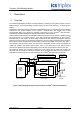
TrustedTM CS300 Bridge Module 1. Description 1.1. Overview TM The CS300 Bridge Module enables connection between a CS300 I/O sub system and the Trusted TMR Processor. Three CS300 Bridge modules replace the three ICCB modules in a CS300 primary chassis. The Bridge module has a fast serial ("Hotlink") interface that transfers command and response packets TM Expander Bus.
TrustedTM CS300 Bridge Module 1.2. Power Distribution Each of the Bridge modules is powered from triple redundant PSUs (situated in a separate chassis) that support the main I/O chassis with 5V, 12V & +/-20Vdc supplies and up to three CS300 extension chassis with 12V and +/-20Vdc only. 1.3. Communication Busses 1.3.1.
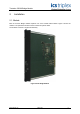
TrustedTM CS300 Bridge Module 2. Installation 2.1. Module Each of the three Bridge modules replaces one of the CS300 ICCB modules. Figure 2 shows the module. The replacement must be carried out with the system offline. The modules consist of a single PCB assembly.
TrustedTM CS300 Bridge Module 2.2. TC-322-02 Interface Cable assembly TM The interface cable connects from the Trusted on the interface cable connector card.
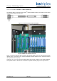
TrustedTM CS300 Bridge Module Figure 5 Trusted TM controller chassis rear view Figure 5 shows a four socket version of the T8312 Expander Interface Adaptor with a TC-301-01 cable TM attached, which connects to a Trusted expander chassis. The Expander Interface Adapter has four TM or seven connections available to individual Trusted Expander chassis or to the CS300 controller chassis using the TC-322-02 Interface Cable Assembly. 2.3.
TrustedTM CS300 Bridge Module The four backplane jumpers 0,1,2,3 (A,B,C) represent the binary address bits 1,2,4 & 8 respectively. A fitted jumper signals a binary digit ‘1’. The address is set to between 2 and 8. On the first CS300 TM chassis (containing the CS300 Bridge Modules), fit jumper 1 (A,B,C) to represent Trusted address '2'. The jumpers on all three sets must be set to the same address. Leave the jumpers as they were on the other CS300 chassis.
TrustedTM CS300 Bridge Module 3. Application TM All CS300 I/O modules are configured using the IEC1131 application Toolset provided with Trusted . This configuration requires entries in the System Configuration (System.INI) for the chassis and modules and their hardware operational parameters, and also in the workbench I/O connection table, for software settings and data connection. 3.1.
TrustedTM CS300 Bridge Module The first chassis to be created is a CS300 8162. This includes the bridge modules in place of the CS300 processors. Choose typeCS300 8162 and select a logical chassis number. This chassis number will define the switch configuration described in section 2.3. Figure 9 CS300 Main Chassis TM The chassis should then be allocated to the Trusted Expander Interface module. Left-click on the left or right end of the CS300 8162 chassis to open the Chassis Connection dialog.
TrustedTM CS300 Bridge Module Figure 12 Jumper Setting This chassis then links into the extension chassis BIC, which is linked to the main CS300 8162 chassis by ribbon cables. To add a BIC chassis, right click again on the background and select CS300 BIC. The switch settings on these chassis should not be changed from their old configuration in the CS300 system.
TrustedTM CS300 Bridge Module Having added all the chassis in the system, the next step is to insert modules. For each module, rightclick on the appropriate chassis slot. Select the module from the list. Figure 14 CS300 Modules On left-clicking the module, the module options are displayed. Figure 15 Module Options If the module has been allocated a Hot Repair partner slot, so that the partner module can take over on failure, then check the Hot Repair Module option.
TrustedTM CS300 Bridge Module 3.2. Board definitions There are no restrictions in the order of the boards set out in the connection table except in cases where TM117-DMX (64-Channel De-Multiplexed Driver) termination cards are configured in the system. These have to be defined before any CS300I/O modules are specified. The DMX cards are TM driven from the Trusted processor module’s serial ports. TM It is also general convention to specify the Trusted table.
TrustedTM CS300 Bridge Module 3.3. Module – 8162 (Bridge Module) DESCRIPTION This definition provides module status for a 8162 primary chassis expansion interface module that TM provides an expansion bridge from Trusted to CS300 systems. The logical module accounts for the 3 physical modules FCR-A, FCR-B and FCR-C. OEM PARAMETERS: OEM parameter Valid numbers Description CHASSIS 2-29 Logical chassis number allocated to the primary CS300 chassis in which the 8162 modules are placed.
TrustedTM CS300 Bridge Module 3.4. Module – bic (bus interface controller) DESCRIPTION This definition provides module status for a PI 651/751 Bus Interface Controller that provides expansion interface for secondary chassis in the CS300 system. The logical module accounts for the 3 physical modules FCR-A, FCR-B and FCR-C. OEM PARAMETERS: OEM parameter Valid numbers Description CHASSIS 2-29 Logical chassis number allocated to the local secondary CS300 chassis in which the BIC modules are placed.
TrustedTM CS300 Bridge Module 3.5. Module – pi632 / pi732 (analogue input module) DESCRIPTION This definition will open a single PI632 or PI732. OEM PARAMETERS OEM parameter Valid numbers Description CHASSIS 2-29 SLOT 1-15 Logical chassis and slot number where the CIO_AI is located.
TrustedTM CS300 Bridge Module 3.6. Module – pi641 / pi741 (analogue output module) DESCRIPTION This definition will open a single PI641 or PI741. OEM PARAMETERS OEM parameter Valid numbers Description CHASSIS 2-29 SLOT 1-15 Logical chassis and slot number where the CIO_AO is located.
TrustedTM CS300 Bridge Module RACK 4: (CALIB) 4 BOOLEAN outputs (one per channel) which determine if the AO output data is taken from RACK 1 (AO) or from RACKs 5-7 (CALIB_x). =0, output data taken from RACK 1 (AO) =1, output data taken from RACKs 5-7 (CALIB_x) RACK 5: (CALIB_A) 4 INTEGER outputs Output data used for Slice A on the AO module. Only used if the corresponding Boolean output in RACK 4 (CALIB) is TRUE. RACK 6: (CALIB_B) 4 INTEGER outputs Output data used for Slice B on the AO module.
TrustedTM CS300 Bridge Module 3.7. Module – pi616_5 / pi616_9 / pi716 / pi717 (digital input module) DESCRIPTION This definition will open a single PI616 type 5 or PI616 type 9 or PI716 or PI717. OEM PARAMETERS OEM parameter Valid numbers Description CHASSIS 2-29 SLOT 1-15 Logical chassis and slot number where the module is located.
TrustedTM CS300 Bridge Module 3.8. Module – pi626 / pi726 (digital output module) DESCRIPTION This definition will open a single PI626 or PI726. OEM PARAMETERS OEM parameter Valid numbers Description CHASSIS 2-29 SLOT 1-15 Logical chassis and slot number where the CIO_DO is located.
TrustedTM CS300 Bridge Module RACK 3: (FAULTS) 4 INTEGER inputs Word 1 Discrepancy errors, channels 1-16 (bit 0 = channel 1) Word 2 Discrepancy errors, channels 17-32 (bit 0 = channel 17) Word 3 LFD errors, channels 1-16 (bit 0 = channel 1) Word 4 LFD errors, channels 17-32 (bit 0 = channel 17) NOTES: Discrepancy errors will only be checked if the DO module has a configured DI monitor module.
TrustedTM CS300 Bridge Module 3.9. Module – pi627 / pi727 / pi627_fs / pi727_fs (digital output module) DESCRIPTION This definition will open a single PI627 or PI727. If the module is configured as 3-2-1 then the ‘_fs’ version is required and the option must also be marked in the system configuration for this module. OEM PARAMETERS OEM parameter Valid numbers Description CHASSIS 2-29 SLOT 1-15 Logical chassis and slot number where the CIO_DO is located.
TrustedTM CS300 Bridge Module RACK 3: (FAULTS) 4 INTEGER inputs Word 1 Discrepancy errors, channels 1-16 (bit 0 = channel 1) Word 2 Discrepancy errors, channels 17-32 (bit 0 = channel 17) Word 3 LFD errors, channels 1-16 (bit 0 = channel 1) Word 4 LFD errors, channels 17-32 (bit 0 = channel 17) NOTES: Discrepancy errors will only be checked if the DO module has a configured DI monitor module.
TrustedTM CS300 Bridge Module 3.10. Module – dmx_m (de-multiplexed display driver) DESCRIPTION This definition will open a single TM117-DMX Master. OEM PARAMETERS OEM parameter Valid numbers Description PORT_A 1-3 MP serial port number for the DMX chain primary link PORT_B 0 or 2/3 MP serial port number for the DMX chain secondary link (=0 disables the secondary link) PHYSICAL MODULE: RACK 1: (DMX) 1 BOOLEAN output not used NOTES: The dmx_m module must be defined before the dmx_o modules.
TrustedTM CS300 Bridge Module 3.11. Module – dmx_o (de-multiplexed display driver card) DESCRIPTION This definition will open a single TM117-DMX output card. OEM PARAMETERS OEM parameter Valid numbers Description DMX_BOARD_ID 1-64 DMX board ID PHYSICAL MODULE: RACK 1: (DMX) 64 INTEGER outputs Valid values: 0 = Off 1 = Slow flash on/off 2 = Fast flash on/off 3 = On (steady) 4+ = Invalid (will result in output being off) NOTES: The dmx_m module must be defined before the dmx_o modules.
TrustedTM CS300 Bridge Module 4.
TrustedTM CS300 Bridge Module 4.1. Front Panel Indicators and Controls 4.1.1. Tx & Rx Indicators Flashing amber LEDs indicate active transmit and receive communications on the Expander Bus. 4.1.2. Health Indicator A steady green LED indicates a fault-free Bridge module; an extinguished LED indicates a fault. 4.1.3. On-Line Indicator and Switch Raising and releasing the on/off-line switch momentarily takes the module off-line, which is mirrored by the steady On/Off state of the amber On-Line LED.
TrustedTM CS300 Bridge Module 5. Fault Finding and Maintenance TM The Trusted TMR Processor provides fault monitoring, self test and diagnostics functions. TM Fault Detection within a Trusted TM Trusted / CS300 system can be categorised into four regions – TMR Processor and Expander Hardware CS300 Bridge Hardware CS300 I/O Hardware User Application TM Using current Trusted methods for detection of faults, the TMR Processor can monitor for failures up to the Expander section.
TrustedTM CS300 Bridge Module 6. Specifications Supply Voltage 5.
TrustedTM PD-8162 Issue 02 Feb 10 PD-8162 34