
Installation Owner's manual

Rockwell Automation Publication CHPS-UM001D-EN-P - July 2014 97
Start-up Guide for CHPS-Series Stage with Ultra3000 Drive and Ultraware Software Appendix D
Oscilloscope Verification
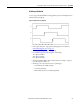
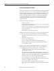
Correct stage and Ultra3000 drive wiring yields the phase relationship shown in
Hall Oscilloscope Diagram.
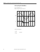
Figure 26 - Hall Oscilloscope Diagram
• Data capture direction - stage positive phasing direction as shown in
Positive Phasing Direction
on page 96.
• S1 leads S2 leads S3, 120° electrical spacing.
• For standard stages have following phase relationship:
S1 in phase with W-U
S2 in phase with U-V
S3 in phase with V-W
• Hall probe GND to Hall common and, for W-U for example, coil probe
tip = W and probe GND = U
• If wiring is correct the causes for incorrect phasing are:
– non-standard coil or Hall assembly
– coil electrical problem
– Hall module electrical or mechanical problem
S1
S2
S3
0° 60° 120° 180° 240° 300° 360°